NL
NL
Het aansluiten van capacitieve schakelaars van industriële kwaliteit vereist precisie: een gemiste aardverbinding kan ervoor zorgen dat uw bedieningspaneel niet meer reageert. In deze uitgebreide handleiding leert u stap voor stap hoe u capacitieve schakelaars aansluit, de benodigde gereedschappen voorbereidt, integreert met PLC's of microcontrollers, veelvoorkomende problemen oplost en best practices uit de industrie implementeert voor veeleisende omgevingen. We beginnen met uit te leggen wat een capacitieve schakelaar is en hoe deze werkt, waarna we ingaan op essentiële gereedschappen en materialen, basis- en geavanceerde bedradingsconfiguraties, integratietechnieken, strategieën voor het oplossen van problemen, omgevingsfactoren en tot slot waarom de capacitieve schakelaars van Langir ongeëvenaarde duurzaamheid en aanpassingsmogelijkheden bieden. Laten we ervoor zorgen dat uw touchsensorproject vlekkeloos verloopt.
Capacitieve schakelaars begrijpen: principes en werking
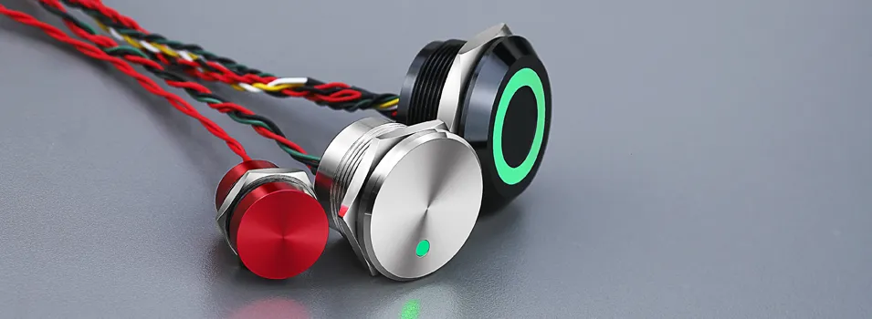
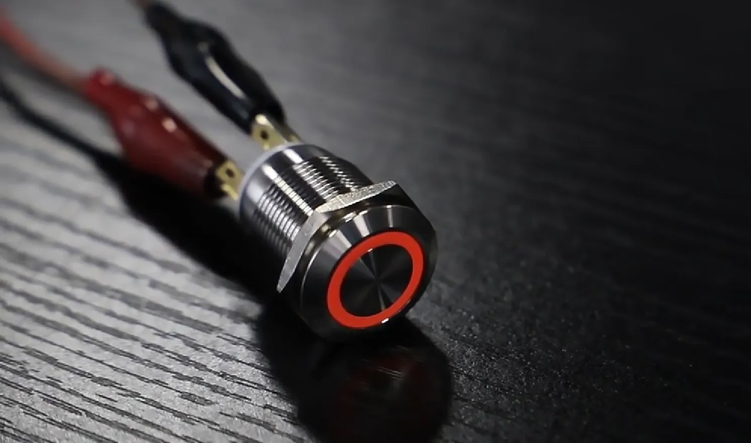
Een capacitieve schakelaar is een elektronisch apparaat dat aanraking detecteert door veranderingen in capaciteit te registreren. Het werkt zonder bewegende onderdelen en biedt daardoor een ongeëvenaarde betrouwbaarheid. Binnenin de schakelaar ontstaat een nauwkeurig elektrisch veld tussen geleidende elektroden. Wanneer een vinger dat veld verandert, registreert het ingebouwde circuit een “aanraking” en schakelt het de output om. Door bijvoorbeeld met uw vinger over een industrieel paneel te schuiven, kunt u een relais activeren zonder mechanische slijtage, waardoor robuuste, onderhoudsvrije interfaces mogelijk zijn.
Vraag een offerte aan voor capacitieve schakelaars op maat van Langir
Kernprincipes van capacitieve detectie
Capacitieve schakelaars werken door veranderingen in capaciteit te detecteren, een fundamentele elektrische eigenschap die het vermogen van een systeem om lading op te slaan meet. Wanneer een vinger de sensor nadert, verandert het elektrische veld, waardoor de schakelaar wordt geactiveerd. Deze technologie zorgt voor consistente, betrouwbare schakeling zonder bewegende onderdelen, waardoor deze zeer geschikt is voor industriële toepassingen.
Morita, T., “Capacitieve sensoren: ontwerp en toepassingen” (2018)
Dit onderzoek biedt cruciale inzichten in de basisprincipes van capacitieve detectie, die essentieel zijn om te begrijpen hoe capacitieve schakelaars werken.
Capaciteit uitgelegd: de rol ervan bij aanraakdetectie
Capaciteit is de elektrische eigenschap die het vermogen van een systeem om lading op te slaan en vrij te geven meet, en vormt de kern van capacitieve aanraakdetectie. Wanneer u het sensoroppervlak aanraakt, draagt uw lichaam bij aan de totale capaciteit, waardoor een minieme spanningsverschuiving ontstaat die door de sensor-IC van de schakelaar wordt versterkt en gedetecteerd. Deze verandering in capaciteit is het signaal dat een succesvolle activering aan de logica van de schakelaar doorgeeft, waardoor capaciteit fundamenteel is voor aanraakgevoelige bediening.
Elektrodefunctionaliteit bij capacitieve aanraakdetectie
Elektroden fungeren als sensorplaten die achter een paneeloppervlak zijn ingebouwd en continu minieme spanningsschommelingen monitoren die worden veroorzaakt door de nabijheid of het contact van een vinger.
- Ze vormen een nauwkeurig ladingsreservoir dat verschuift wanneer een geleidend voorwerp nadert.
- Een gespecialiseerde sensor-IC meet nauwkeurig de verandering in de lading die door deze elektroden wordt opgeslagen.
- De drempels voor aanraakdetectie kunnen nauwkeurig worden ingesteld om valse triggers door omgevingsfactoren zoals stof of vochtigheid te voorkomen.
Instelbare drempels garanderen consistente prestaties in fabrieksinstellingen, en deze adaptieve elektroden zorgen ervoor dat uw capacitieve schakelaar zeer responsief en betrouwbaar blijft.
Capacitieve versus mechanische schakelaars: belangrijke industriële voordelen
Hieronder vindt u een vergelijking van de belangrijkste ontwerpkenmerken, voordelen en werkingsmechanismen die de superieure prestaties van capacitieve schakelaars ten opzichte van mechanische schakelaars in industriële omgevingen benadrukken.
Deze functies zorgen voor een langere levensduur en minimale onderhoudsvereisten, waardoor capacitieve schakelaars de optimale keuze zijn voor zware bedieningspanelen.
Essentiële gereedschappen en materialen voor het bedraden van capacitieve schakelaars
Vraag een offerte aan voor capacitieve schakelaars op maat van Langir
Langir capacitieve schakelaars: modellen voor industriële integratie
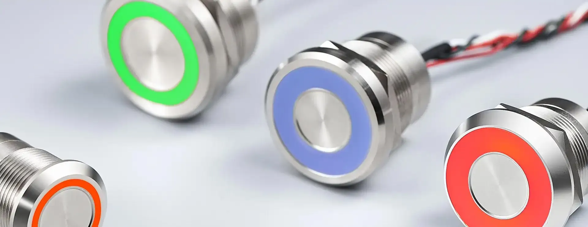
Langir produceert hoogwaardige capacitieve drukknopschakelaars met een diameter van 16 mm, 19 mm en 22 mm, die allemaal zijn vervaardigd volgens de strenge ISO9001:2015-normen en een IP67/IP68-classificatie hebben voor water- en stofbestendigheid.
- CP16-serie (16 mm) – Compact formaat, ideaal voor panelen met beperkte ruimte.
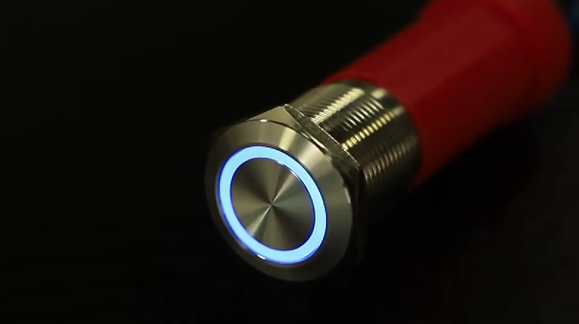
- CP19-serie (19 mm) – Optimale afmetingen met optionele LED-ringverlichting.
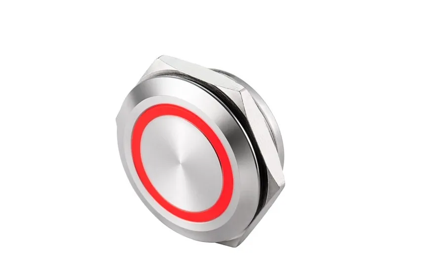
- CP22-serie (22 mm) – Ruim bedieningsgebied met een vandalismebestendige rand.
Elk model biedt een uitzonderlijke levensduur van maximaal 50 miljoen cycli en een instelbare gevoeligheid, waardoor ze perfect geschikt zijn voor industriële bedradingsscenario's die zowel superieure duurzaamheid als naadloze integratie vereisen.
Benodigde gereedschappen en onderdelen voor naadloze bedrading
Om een vlekkeloos proces voor het bedraden van capacitieve schakelaars te garanderen, hebt u het volgende nodig:
- Een gekalibreerde digitale multimeter voor nauwkeurige spanning- en continuïteitscontrole.
- Industriële draadstrippers en -snijders geschikt voor robuuste bekabeling.
- Professionele soldeerbout of gecertificeerd krimptang voor betrouwbare, veilige verbindingen.
- Geïsoleerde 18–24 AWG-bedrading, die een optimale geleiding voor stroom-, aardings- en signaallijnen garandeert.
- Krimpkous of duurzame nylon kabelwartels voor superieure afdichting tegen omgevingsinvloeden.
Door deze gereedschappen bij de hand te hebben, verloopt uw bedradingsproces vlotter en blijft de integriteit van elektrische aansluitingen gewaarborgd, zelfs in de meest veeleisende industriële omstandigheden.
Optimale bedrading en connectoren selecteren voor capacitieve schakelaars
Het kiezen van de juiste kabels en connectoren is van cruciaal belang om signaalverlies en voortijdige systeemstoringen te voorkomen, met name in industriële omgevingen die gevoelig zijn voor trillingen of vocht.
- Gebruik afgeschermde meeraderige kabels voor signaalkabels die in de buurt van motoren of hoogspanningscircuits worden aangelegd.
- Kies M12- of M8-connectoren met IP67-classificatie voor robuuste, plug-and-play-installaties.
- Zorg ervoor dat de kabeldikte voldoet aan de huidige vereisten: 18 AWG voor LED-indicatoren, 22 AWG voor signaalretouren.
Het selecteren van de juiste bedrading garandeert een stabiele signaalintegriteit en verlengt de levensduur aanzienlijk, waardoor de basis wordt gelegd voor nauwkeurige aansluitprocedures.
Basisconfiguraties voor de bedrading van capacitieve schakelaars: een stapsgewijze handleiding
Vraag een offerte aan voor capacitieve schakelaars op maat van Langir
Een 2-draads capacitieve schakelaar aansluiten: stapsgewijze instructies
Voor configuraties waarbij stroom en signaal een gemeenschappelijke lijn delen, dient u deze precieze stappen te volgen:
- Sluit de positieve (+V) aansluiting van uw 12–24 V DC-voeding rechtstreeks aan op de daarvoor bestemde “+”-pin van de schakelaar.
- Sluit de “–/SIG”-pin van de schakelaar aan op het belastingsapparaat, zoals een relaisspoel.
- Maak het circuit compleet door het andere uiteinde van de belasting terug te verbinden met de negatieve (–) pool van de voeding.
Door gebruik te maken van deze 2-draadsopstelling kan de schakelaar bij aanraking stroom door de belasting laten vloeien, waardoor installaties worden gestroomlijnd door een minimalisering van het aantal aansluitpunten.
Bedrading van een 3-draads capacitieve schakelaar: integratie van voeding, aarding en signaal
Een configuratie met drie draden biedt speciale aardings- en signaallijnen, wat zorgt voor schonere en stabielere schakeloperaties:
- +V (12–24 V DC) → “+V”-pin op schakelaar
- 0 V (aarde) → “GND”-pin op schakelaar
- Signaaluitgang (NPN/PNP) → PLC- of controller-ingang
Deze scheiding van aarde en signaal vermindert de gevoeligheid voor ruis aanzienlijk en wordt ten zeerste aanbevolen in geautomatiseerde bedieningspanelen waar nauwkeurige en betrouwbare signaaldetectie van cruciaal belang is.
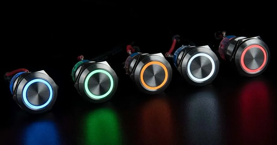
Capacitieve schakelaars met geïntegreerde LED-indicatoren aansluiten
Geïntegreerde LED's geven belangrijke visuele feedback aan operators. Om deze componenten aan te sluiten:
- Voer +V aan op de daarvoor bestemde “+V”-pin van de schakelaar.
- Verbind de “GND”-pin van de schakelaar met de 0 V-gemeenschappelijke aansluiting.
- Sluit de “SIG/OUT”-pin aan op de ingang van uw besturingssysteem.
- Gebruik de speciale “LED+” en “LED–” pinnen, met een stroombeperkende weerstand van 2 mA–10 mA aan de positieve kant.
Door deze bedrading kan de schakelaar oplichten tijdens actieve of stand-bymodi, waardoor de operator beter zichtbaar is in industriële omgevingen met weinig licht of veel activiteit.
Een capacitieve schakelaar aansluiten op een eenvoudige belasting of relais
Voor directe relaisactivering dient u zich aan de volgende aansluitingsrichtlijnen te houden:
- +V → schakel “+V”-pin
- GND → schakel “GND”-pin en negatieve relayspoel
- Schakel “OUT” → relaisspoel positief
- Relay common (COM) en normaal open (NO) contacten in serie geschakeld met uw apparaat
Deze eenvoudige relaisintegratie maakt het mogelijk om met een capacitieve schakelaar efficiënt belastingen met een hoger vermogen aan te sturen zonder dat daarvoor extra interfacemodules nodig zijn.
Capacitieve schakelaars integreren met industriële besturingssystemen
Vraag een offerte aan voor capacitieve schakelaars op maat van Langir
Capacitieve schakelaars aansluiten op PLC's voor geautomatiseerde besturing
De meeste programmeerbare logische controllers (PLC's) zijn ontworpen om digitale inputs van NPN- of PNP-outputs te accepteren. Om een verbinding tot stand te brengen:
- Sluit de “+V”-aansluiting van de schakelaar aan op de 24 V DC-voeding van de PLC.
- Sluit de “GND”-aansluiting aan op de gemeenschappelijke aarding van de PLC.
- Leid het “OUT”-signaal van de schakelaar naar het aangewezen ingangskanaal op uw PLC.
- Activeer invoerfiltering binnen de PLC-software om capacitieve signalen effectief te ontdampen.
Deze directe verbinding garandeert dat uw SCADA- of HMI-systeem aanraakgebeurtenissen onmiddellijk en betrouwbaar kan interpreteren.
Capacitieve aanraaksensoren koppelen aan microcontrollers (Arduino, Raspberry Pi)
Microcontrollers vereisen logische signalen en de juiste spanningsaanpassing. Voor Arduino (5 V):
Gebruik een level-shifter als uw schakelaar werkt op 12–24 V; dit codefragment koppelt de schakelaaruitgang effectief aan een ingebouwde LED en seriële monitor.
Best practices voor het ontwerpen van capacitieve schakelaarinterfaces in industriële panelen
Houd bij het configureren van industriële paneelinterfaces rekening met deze cruciale ontwerpelementen:
- Houd minimaal 5 mm afstand tussen aangrenzende sensoren om signaaloverdracht effectief te voorkomen.
- Gebruik FR4 of metalen achterplaten die specifiek zijn goedgekeurd voor EMI-afscherming achter capacitieve schakelaarafsluitingen.
- Zorg voor een duidelijke markering van de schakelaarposities met duurzame, lasergegraveerde pictogrammen om operators intuïtief te begeleiden.
Deze ontwerpbeslissingen dragen bij aan een strak, zeer betrouwbaar en intuïtief paneelontwerp voor eindgebruikers.
Problemen met bedrading bij capacitieve schakelaars oplossen
Vraag een offerte aan voor capacitieve schakelaars op maat van Langir
Diagnose van een niet-reagerende capacitieve schakelaar
Begin met het oplossen van problemen met deze fundamentele controles:
- Controleer de integriteit van de +V- en GND-aansluitingen met behulp van een gekalibreerde multimeter.
- Controleer of de uitgangsspanning van de schakelaar verandert wanneer deze wordt bediend.
- Controleer alle bedrading grondig op losse krimpkousen of beschadigde isolatie.
Als de stroom- en aardingsaansluitingen zijn gecontroleerd, maar er geen signaalverandering wordt waargenomen, overweeg dan om een schakelaar te vervangen door een schakelaar waarvan bekend is dat deze goed werkt, om zo eventuele hardwarefouten effectief te isoleren.
Problemen met valse activering en gevoeligheid oplossen
Valse activeringen zijn vaak het gevolg van omgevingsfactoren. Voer de volgende corrigerende maatregelen door:
- Stel de gevoeligheid nauwkeurig in via de ingebouwde trimpotentiometer.
- Breng afschermende tape of een geaarde metalen folielaag aan achter het paneel.
- Verhoog de debounce- of filterdrempels van de software binnen uw besturingssysteem.
Door de gevoeligheid en afscherming goed in te stellen, worden fantoombereikingen effectief voorkomen en wordt een stabiele, betrouwbare werking gegarandeerd.
Beperking van elektrische ruis en aardingsproblemen bij bedrading
Industriële omgevingen gaan vaak gepaard met aanzienlijke elektrische ruis. In deze tabel worden veelvoorkomende ruisbronnen en effectieve technieken om deze te verminderen op een rijtje gezet:
Door afschermingen correct te aarden en eenvoudige onderdrukkingscomponenten toe te voegen, wordt een betrouwbare werking van de schakelaar hersteld en gehandhaafd.
Best practices voor het aansluiten van capacitieve schakelaars in veeleisende industriële omgevingen

Vraag een offerte aan voor capacitieve schakelaars op maat van Langir
Bedrading Waterdichte en vandalismebestendige capacitieve schakelaars
Houd u aan deze specifieke bedradingsrichtlijnen voor afgedichte installaties:
- Leid alle bekabeling door IP68-gecertificeerde wartels die zijn uitgerust met dubbele O-ringen.
- Breng een hoogwaardige siliconenpottingcompound aan op alle blootliggende soldeerverbindingen.
- Zorg ervoor dat de moeren van de rand precies volgens de specificaties van de fabrikant worden aangedraaid om de IP-classificatie te behouden.
Deze aanpak zorgt ervoor dat de waterdichte afdichting van de schakelaar behouden blijft en verhoogt de weerstand tegen manipulatie of fysiek misbruik.
Aarding- en afschermingstechnieken voor verbeterde betrouwbaarheid
Effectieve afscherming en aarding zijn cruciaal om te voorkomen dat strooielektromagnetische velden de aanraakdetectie verstoren:
- Sluit alle kabelafschermingen goed aan op de aarding van het paneelchassis.
- Plaats een laag koperfolie achter het paneel en zorg ervoor dat deze op het aardpotentiaal van de sensor zweeft.
- Sluit de schakelaarbehuizing rechtstreeks aan op de paneelaarding om potentiaalverschillen te elimineren.
Door deze stappen te volgen, wordt een stabiel referentiepunt vastgesteld en wordt effectief voorkomen dat verdwaalde EMI valse activeringen veroorzaakt.
Zorgen voor naleving van elektrische veiligheidsnormen en certificeringen
Naleving van industriële bedradingsnormen
Het naleven van erkende normen zoals IP65-IP68 voor bescherming tegen het binnendringen van stof en water, en CE/RoHS voor elektrische veiligheid, is van cruciaal belang voor het garanderen van de betrouwbaarheid en naadloze interoperabiliteit van capacitieve schakelaars in industriële omgevingen. Deze certificeringen bevestigen dat de bedradingspraktijken voldoen aan strenge wereldwijde industriële veiligheidseisen.
Internationale Elektrotechnische Commissie (IEC), "Beschermingsgraden van behuizingen (IP-code)".
Deze norm is zeer relevant, omdat deze nauwkeurig de specifieke vereisten voor milieubescherming beschrijft, een cruciaal aandachtspunt bij het gebruik van capacitieve schakelaars in veeleisende industriële omgevingen.
Waarom capacitieve schakelaars van Langir de optimale keuze zijn voor uw bedradingsbehoeften
Vraag een offerte aan voor capacitieve schakelaars op maat van Langir
Langir's maatwerk- en OEM-bedradingsoplossingen
Langir is gespecialiseerd in het leveren van oplossingen op maat, waaronder:
- Aangepaste randmaterialen (bijv. roestvrij staal, acryl, PBT) ontworpen voor specifieke blootstelling aan chemicaliën.
- Gespecialiseerde kabellengtes en connectoruitgangen die precies zijn afgestemd op de machine-indeling.
- Precisie-logo-etsing en kleurgecodeerde LED's voor onderscheidende merkinterfaces.
Deze OEM-services maken een naadloze integratie van schakelaars in uw apparatuur mogelijk zonder dat dit ten koste gaat van het ontwerp of de functionaliteit.
Langir's toewijding aan duurzaamheid en kwaliteit in bedradingstoepassingen
Onze niet-aflatende toewijding aan kwaliteit en betrouwbaarheid is geworteld in strenge processen:
- ISO9001:2015-gecertificeerde productielijnen, met 100% elektrische en visuele inspectie.
- Uitgebreide zoutsproeitests en levensduurtests, waarbij de prestaties tot 50 miljoen bedieningscycli zijn gevalideerd.
- Volledige naleving van de CE-, RoHS- en REACH-richtlijnen, waardoor superieure prestaties en veiligheid worden gegarandeerd.
Deze toewijding aan certificering en testen garandeert de levering van componenten waarop u jarenlang kunt vertrouwen voor een ononderbroken, hoogwaardige werking.
Bulkbestellingen of technische ondersteuning voor Langir-schakelaars aanvragen
Bent u klaar om uw assemblageproces te optimaliseren of geavanceerde oplossingen voor maatwerkbekabeling te verkennen? Wij nodigen u uit om Neem contact op met Langir voor capacitieve schakelaars in bulk en OEM-diensten door onze speciale website te bezoeken Neem contact met ons op pagina. Ons deskundige technische team staat klaar om u te begeleiden bij de keuze van het optimale model, geavanceerde best practices voor bedrading en concurrerende volumeprijzen om precies aan uw productiedoelstellingen te voldoen.
Het bedraden van capacitieve schakelaars hoeft geen complexe onderneming te zijn als u gestructureerde stappen volgt, de juiste gereedschappen selecteert en best practices toepast voor ruisonderdrukking en milieubescherming. Van eenvoudige tweedraads aansluitingen tot PLC-integratie en afdichting voor veeleisende omgevingen: deze uitgebreide gids biedt een essentiële routekaart naar betrouwbare, duurzame touch-interfaces. Door te kiezen voor de gecertificeerde, aanpasbare capacitieve schakelaars van Langir en gebruik te maken van onze uitgebreide expertise, minimaliseert u effectief de downtime en vergroot u het vertrouwen van de operator aanzienlijk. Het is nu tijd om uw industriële panelen aan te sluiten, deze cruciale verbindingen tot stand te brengen en de toekomst van robuuste, onderhoudsvrije industriële besturing te omarmen.