
 EN
EN
Electrical switch symbols are crucial for understanding the network of circuits that power our lives. These symbols visually represent how a switch functions within a circuit and help engineers and technicians effectively communicate and design electrical systems. Electrical switches are in high demand due to their vital role in our daily lives. That’s why the electric switch industry surpassed $13 billion in 2021 and expects to grow even further.
This article will explore the most common electrical switches, their symbols, and their meanings, providing a comprehensive understanding of this aspect of electrical engineering.
Definition of Electrical Switch Symbols
Electrical switch symbols are graphical representations used in circuit diagrams to depict different types of switches and their functions. These symbols provide a standardized and universal language for engineers, electricians, and technicians to communicate and understand switches’ position and actions in electrical circuits.

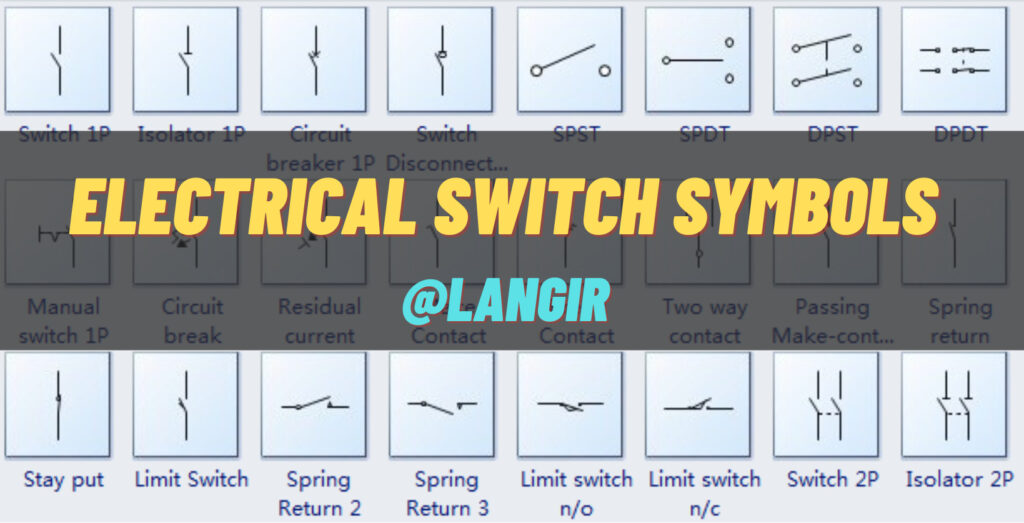
Types of Electrical Switch Symbols
Following are the types of electrical switch symbols that you must be aware of. Most of them are being used as touch switches in modern devices.
Single-pole, single-throw (SPST) Switch Symbol
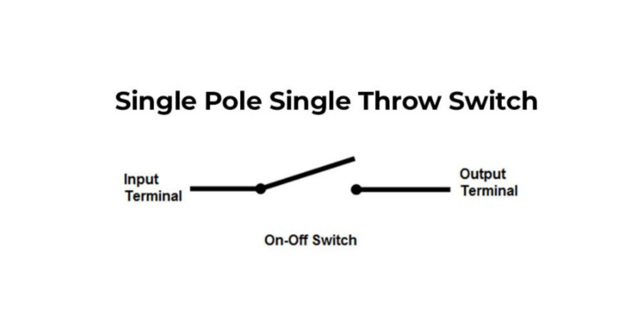
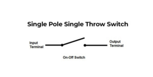
A single-pole, single-throw (SPST) switch controls the current flow in a single path, with one input and one output connection. When SPST is closed, the circuit is complete, allowing the current to flow through. On the other hand, the circuit is interrupted when SPST is open, preventing the flow of the current.
The SPST switch is commonly used for basic on/off applications, where simple control over the circuit is required. It is represented by a single line in electrical circuit diagrams, indicating the current path when the switch is closed.
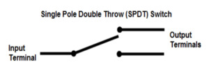
Single-pole, double-throw (SPDT) switch
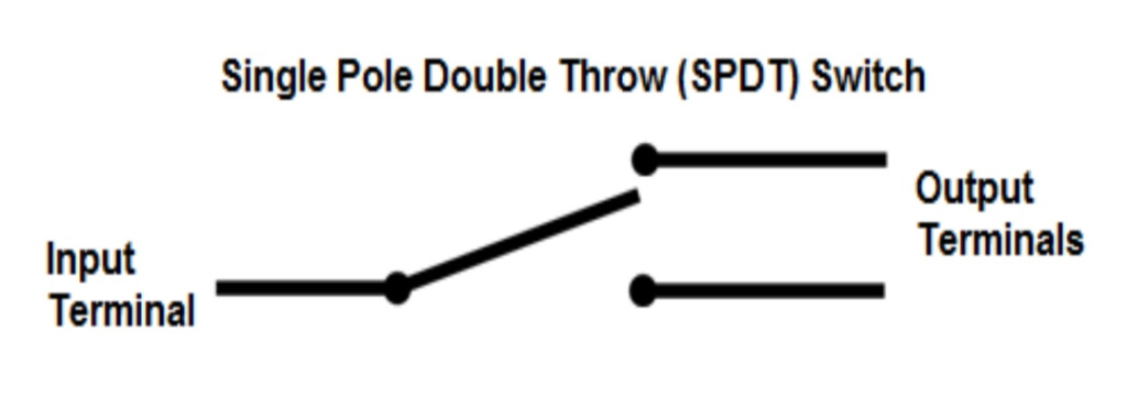
A single-pole, double-throw (SPDT) can connect one input to either of two outputs. It has one input and two output connections. The connection of input to output depends upon the position of the switch.
The SPDT switch allows for alternate connections or functions, providing flexibility in circuit design. It is commonly used when choosing between two different paths or circuits. In electrical circuit diagrams, the SPDT switch is represented by a single line with a “T” shape at one end.
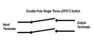
Double-pole, single-throw (DPST) switch
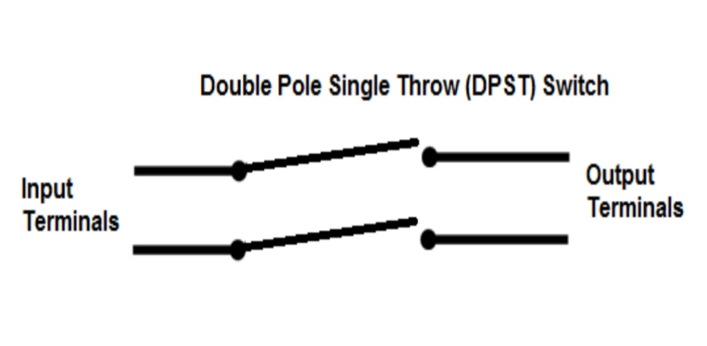
A double-pole, single-throw (DPST) switch simultaneously controls the flow of current in two separate circuits. When closed, both input connections are connected to the output, and the current flows through both circuits. Both input connections are disconnected from the output when the switch is open, interrupting the current flow in both circuits.
The DPST switch is commonly used in applications where the synchronization of two circuits is required, such as controlling two independent devices or components. In electrical circuit diagrams, the DPST switch is represented by two lines with a shared endpoint.
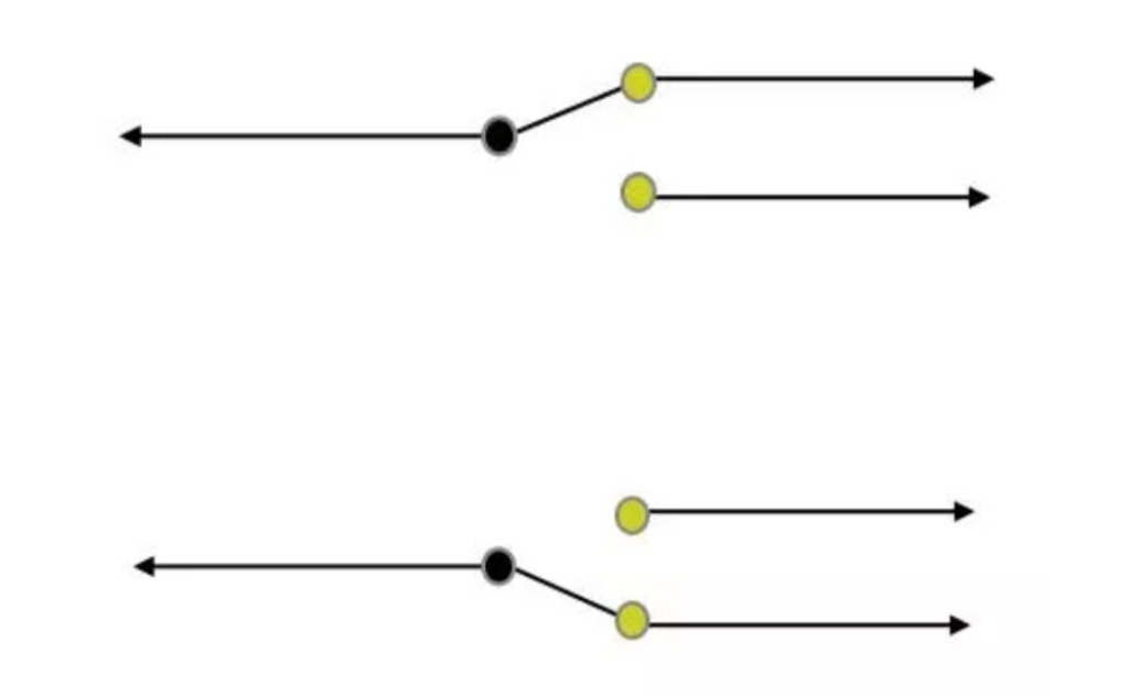
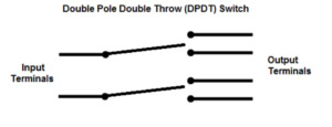
Double-pole, double-throw (DPDT) switch
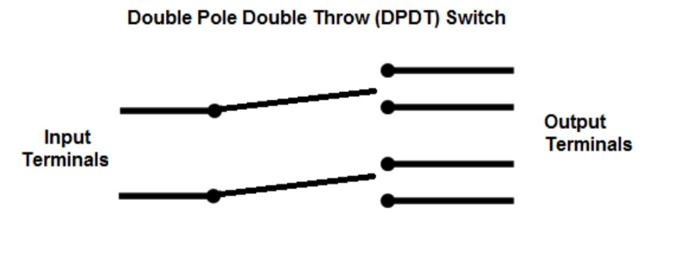
A double-pole, double-throw (DPDT) provides independent control over two circuits with two input and output connections. Its multiple positions allow for different combinations of connections between the inputs and outputs. The connections with inputs and outputs keep changing as the position of the DPDT changes.
It makes DPDT an ideal choice for reversing the direction of a motor or toggling between two different functions. In electrical circuit diagrams, the DPDT switch is represented by two lines with a shared endpoint and a “T” shape at the other end of each line.
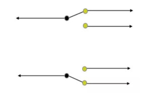
Three-Way Switch
A three-way switch is commonly used in lighting circuits which can be used to control a light fixture from two different locations. When one switch is in the “on” position, the other can turn the light on or off.
It has one common and two traveler terminals. The circuit is completed by connecting the common terminal to one of the traveler terminals, and the light turns on.
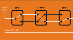
Four-Way Switch
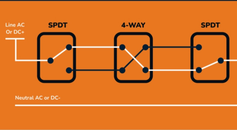
A four-way switch works with three-way switches to manage the illumination of a single light fixture from three or more locations. You can control the light from multiple points using it. Turning the light on or off from any of the connected locations is possible by interconnecting it with the traveler wires of the three-way switches.
This switch is particularly useful in larger areas or spaces with multiple entryways, as it facilitates the convenience of controlling the light from various points. All the modern electronic devices that we use today contain these switches. For instance, capacitive touch switches are widely used in consumer electronics, solar photovoltaic applications, mobile terminal tablets, etc.
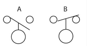
Float Switch Symbol
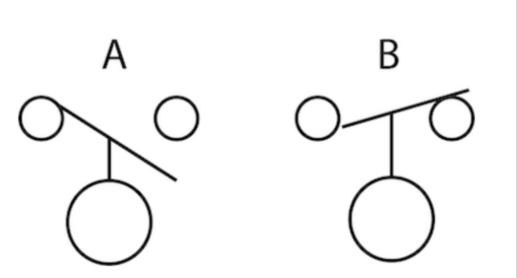
The float switch symbol either represents a normally open or a normally closed state. The “A” diagram is the normally open state, while the “B” diagram is the normally closed state.
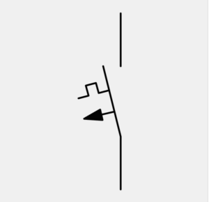
Thermal Magnetic Switch Symbol

The thermal magnetic switch incorporates both electromagnetic and thermal breaking. The electromagnet breaks the circuit instantly during huge current spikes.
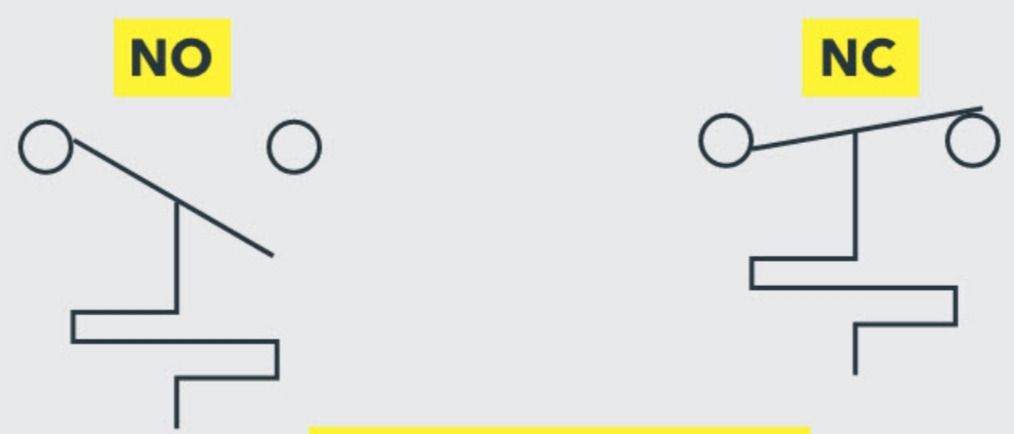
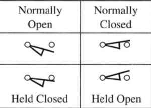
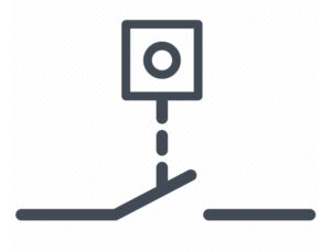
Limit Switch Symbol
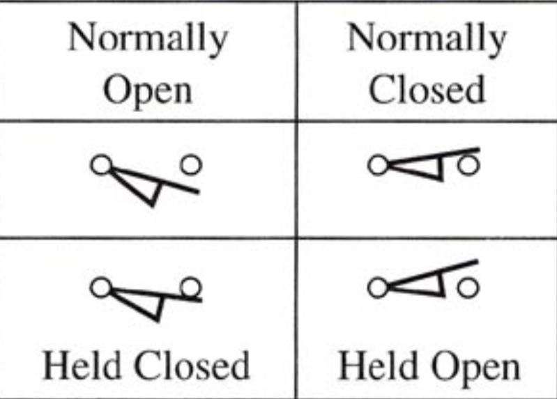
The limit switch is usually represented as normally open, normally closed, held open, and held closed.
Differential Switch Symbol
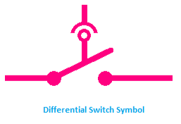
A differential switch symbol shows the difference between phase line current and neutral line current. The circuit breaks if there is any difference in the current.
Pulse Counter Switch

The pulse counter switch symbol shows that the circuit is activated whenever the pulse counter reaches a certain value.
Rotary Switch Symbol
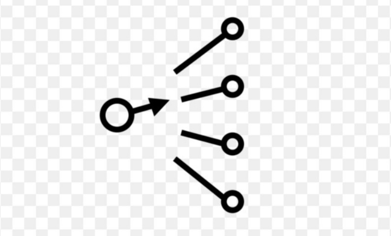
The knob of this symbol rotates around its axis and switches the common terminal to any of the output terminals.
Limit Switch Symbol
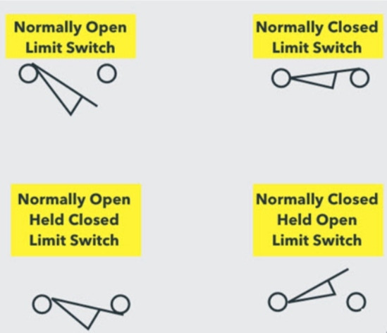
The limit switch symbol has an arm that causes switch contacts to change positions when it’s actuated.
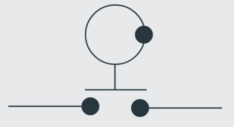
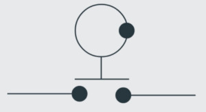
Pressure Switch Symbol

The pressure switch symbol has a circle either connected or disconnected to a line showing the opening or closing of the circuit respectively.
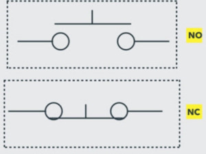
Temperature Switch Symbol
The temperature switch symbol depicts the normally open and normally closed states at certain temperatures. The circuit becomes normally closed only when the temperature falls below the trip point.
Joystick Switch Symbol
The circle and the dot in this symbol have the joystick lever direction, which is needed to actuate the contact.
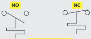
Push Button Switch Symbol
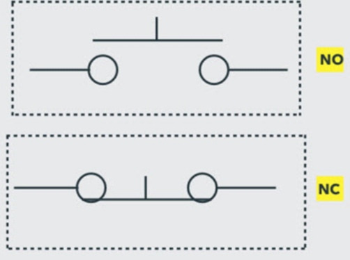
The push button switch symbol shows the position of the push button. The normally open state shows the button pulled out, while the normally closed state shows the button pressed.
Bipolar Transistor Symbol
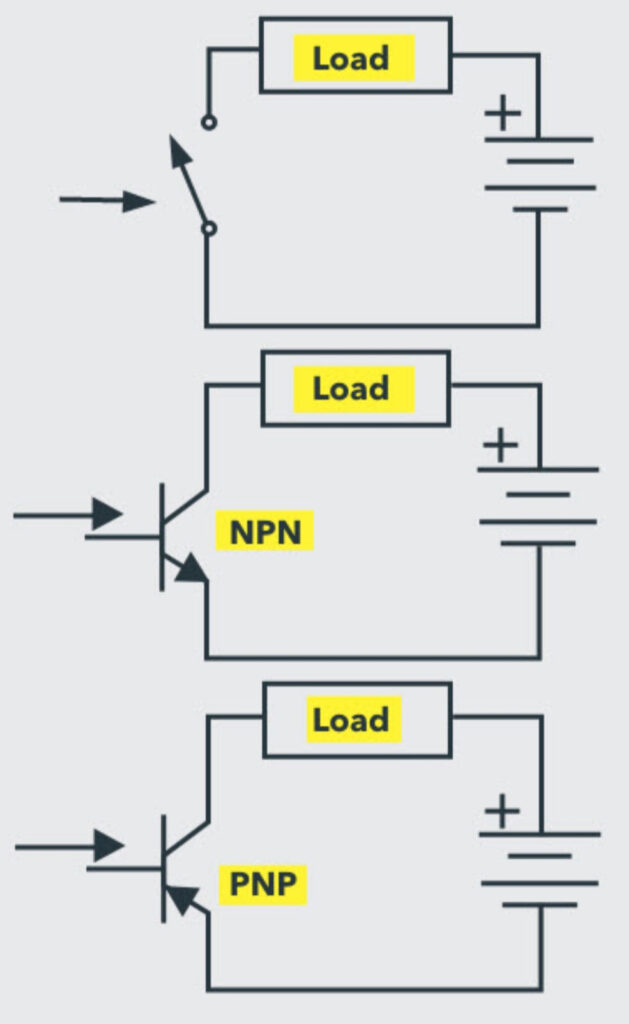
When sufficient current is applied, the transistor symbol shows that both NPN and PNP transistors are operated, and the switch is turned on. On the other hand, it is turned off when the base current is absent.
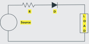
Power Diode
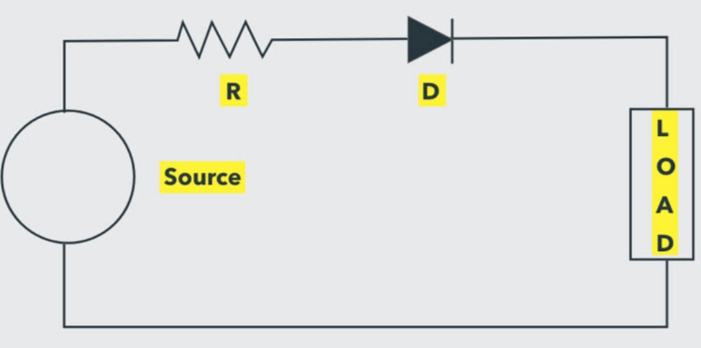
The power diode symbol shows the conduction and blockage of current. Electricity flows through the circuit when the voltage is greater than the threshold level. On the other hand, it’s blocked when the cathode terminal is made positive with respect to the anode and the PN junction is reverse-biased.
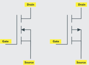
MOSFET Switch Symbol

The symbol of the MOSFET switch represents Drain, Source, Gate, and Body terminals. The source and body terminals are always connected.
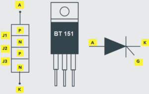
Silicon Controlled Rectifier (SCR) Symbol

The SCR symbol represents four alternative P and N layers, forming J1, J2, and J3 junctions at their boundaries.
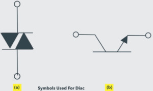
Diode AC Switch (DIAC) Symbol

This symbol shows the two directions in which DIAC can be operated. In order to start conduction, the voltage should cross the break-over voltage point.
Triode AC (TRIAC) Switch Symbol
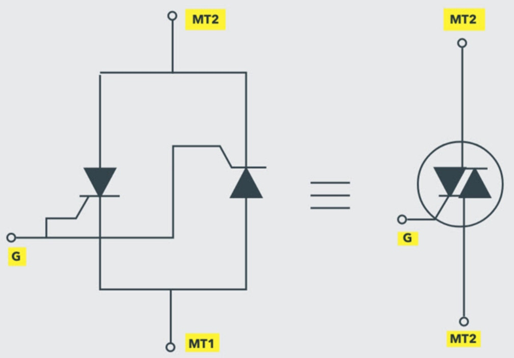
The TRIAC symbol has two antiparallel thyristors on the left side with a common gate. It has a total of three terminals called MT1, MT2, and MT3.
Insulated Gate Bipolar Transistor (IGBT) Symbol
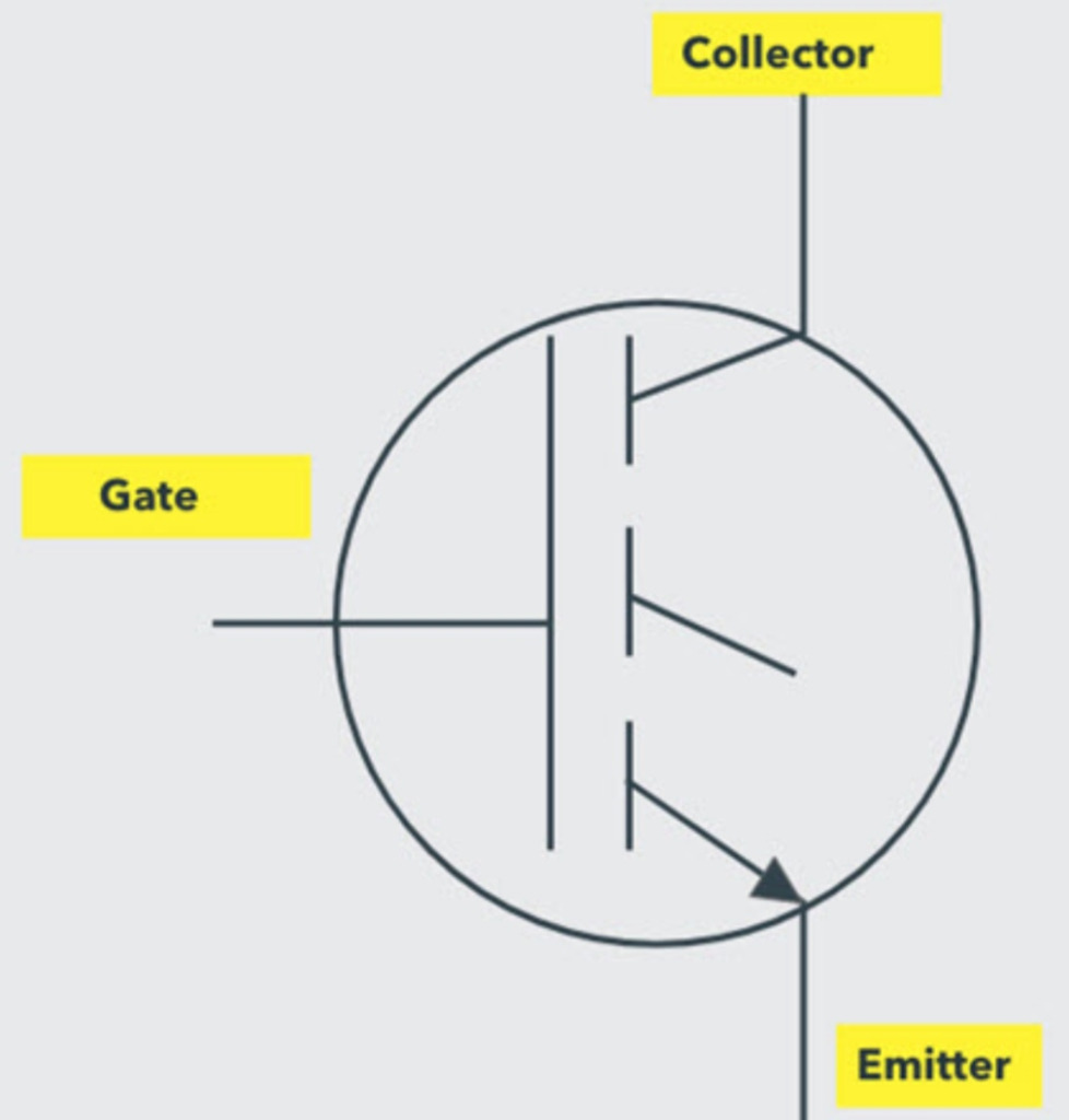
The IGBT symbol has three terminals called Collector, Gate, and Emitter. It can be turned on by passing voltage between Collector and Gate and off by reducing the voltage between Gate and Emitter to zero.
Quick Table of Electrical Switch Symbols
Here’s a quick table of electrical switch symbols with their short descriptions;
| Symbol | Description |
 | Single Pole, Single Throw (SPST) Switch |
 | Single Pole, Double Throw (SPDT) |
 | Double Pole, Single Throw (DPST) |
 | Double Pole, Double Throw (DPDT) |
 | Three Way Switch |
 | Four Way Switch |
 | Float Switch |
 | Thermal Magnetic Switch |
 | Limit Switch Limit Switch |
| Differential Switch Differential Switch |
 | Pulse Control Switch Pulse Control Switch |
 | Rotary Switch Rotary Switch |
 | Limit Switch |
 | Pressure Switch |
 | Temperature Switch |
 | Joystick Switch |
 | Push Button Switch |
| Bipolar Transistor |
 | Power Diode |
 | MOSFET Switch |
 | SCR Switch |
 | DIAC Switch |
 | TRIAC Switch |
| IGBT Switch |
Understanding the Significance of Electrical Switch Symbols
The Importance of Standardized Symbols in Electrical Engineering
Electrical switch symbols are a visual language that engineers, electricians, and technicians can universally understand. It ensures clear and accurate interpretation of electrical diagrams, schematics, and plans.
By using standardized switch symbols, professionals can easily identify and differentiate between different types of switches and understand their configurations & capabilities. It is essential for designing, installing, and troubleshooting electrical systems.
Consistent use of switch symbols promotes effective communication and collaboration among team members involved in electrical projects. It facilitates information sharing, enabling smoother coordination and reducing the chances of errors or misunderstandings.
Moreover, electrical switch symbols enhance safety in electrical systems. Clear and recognizable symbols help ensure proper installation, maintenance, and operation of switches, minimizing the risk of electrical hazards, equipment damage, or operational failures.
How Switch Symbols Represent the Behavior of Switches in Circuits
Switch symbols represent the behavior of switches in circuits by conveying key information about their functionality and connections. They provide a concise visual representation of how switches operate within electrical systems.
When the switch is closed or in the “on” position, the symbol shows a connection between the relevant terminals or lines. Conversely, when the switch is open or in the “off” position, the symbol depicts a gap or break in the connection.
Secondly, they convey the specific configuration of the switch. For example, a single-pole, single-throw (SPST) switch symbol has a single line representing the current flow path when closed. In contrast, a double-pole, double-throw (DPDT) switch symbol has multiple lines and connections to illustrate its dual-pole and dual-throw characteristics.
Furthermore, switch symbols depict the terminals or contacts associated with the switch. This information helps engineers and technicians understand how to connect the switch within a circuit, ensuring proper operation and control.
Reading and Interpreting Switch Symbols in Electrical Schematics
Here are some key steps to effectively interpret switch symbols in electrical schematics:
- Look for symbols such as an SPST, SPDT, DPST, or DPDT switch. Familiarize yourself with the shape and design of each symbol.
- Pay attention to the lines, dots, or arrows in the symbol as they indicate the different terminals and their connections.
- Switch symbols often show different positions or states typically labeled as “on” or “off.” The lines or dots within the symbol indicate them.
- Analyze how the switch connects to resistors, lamps, or power sources, to understand its role in the circuit.
- Trace the signal path through the switch symbol to understand how it affects the circuit. Pay attention to the connections between terminals and the open or closed state of the switch.
Applications of Electrical Switch Symbols
Residential Electrical Wiring
Electrical switch symbols in residential electrical wiring represent switches and their configurations in circuit diagrams.
- They are crucial for thermal protection, lighting control, fan control, appliance control, outlet control, multi-way switching, circuit design, and planning.
- Switch symbols accurately depict the placement and type of switches used in residential wiring, facilitating proper control and operation of lighting fixtures, ceiling fans, appliances, and outlets.
- They help electricians and homeowners understand the wiring layout and ensure safe & efficient electrical installations in residential buildings.
Industrial Control Systems
Electrical switch symbols in industrial control systems are used in circuit diagrams and control schematics to represent switches.
- These symbols are essential for motor control, process control, safety systems, control panels, and interfacing with programmable logic controllers (PLCs).
- They enable the accurate depiction of switches in complex control circuits, aiding in design, documentation, and troubleshooting.
Electronic Circuits and Devices
Electrical switch symbols in electronic circuits and devices represent switches in logic circuits, integrated circuits (ICs), and physical switches in electronic devices.
- These symbols enable signal routing, selection, and control, facilitating logical operations and device functionality.
- They are used in circuit prototyping for manual control during testing and development.
- Additionally, switch symbols are employed in circuit simulation software to model and simulate switch behavior and its impact on circuit performance.
Overall, they play a vital role in accurately representing and understanding the switches used in electronic circuits and devices.
Common Mistakes to Avoid with Electrical Switch Symbols
Confusing Switch Symbols with Other Electrical Symbols
One common mistake is mixing switch symbols with electrical symbols in a circuit diagram. Understanding the specific symbol for switches and differentiating them from symbols representing resistors, capacitors, or other components is crucial. Misinterpreting or using incorrect symbols can lead to confusion and incorrect circuit representations.
Misinterpreting Switch Positions in Circuit Diagrams
Switch symbols in circuit diagrams indicate the position of the switch, such as open or closed. Misinterpreting these positions can lead to errors in understanding the circuit’s intended operation. It is essential to carefully analyze them to accurately reflect whether the switch is on or off in the circuit.
Neglecting to Label or Annotate Switch Symbols
Another mistake is failing to provide clear labels or annotations for switch symbols. Without proper labeling, it becomes challenging to identify the purpose and function of each switch in the circuit. Adequate labeling and annotation help improve the clarity and comprehension of the circuit diagram, making it easier for others to understand and work with the circuit.
Conclusion
Electrical switch symbols play a vital role in understanding and designing electrical circuits. They serve as a visual language that allows engineers and technicians to communicate and interpret circuit diagrams effectively. By familiarizing yourself with these symbols, you can decipher complex circuitry, troubleshoot issues, and design innovative solutions.
Frequently Asked Questions (FAQs)
Q. What is the purpose of labeling electrical switch symbols in circuit diagrams?
Labeling electrical switch symbols in circuit diagrams provides additional information about the switch, such as its function or connection to specific components or circuits. Labels can indicate the switch’s position, state (e.g., open or closed), or other relevant details for understanding the circuit’s operation.
Q. Are there any standards or guidelines for drawing electrical switch symbols?
Yes, organizations like the Institute of Electrical and Electronics Engineers (IEEE) provide standards for symbol representation in electrical circuit diagrams. They ensure consistency and clarity in communication across different industries and countries.
Q. How do I read electrical switch symbols?
Typically, switch symbols consist of various shapes, lines, and arrows. The annotations may include letters or numbers to indicate specific switch functionalities. By referring to a key provided alongside the diagram, you can decipher the meaning of each symbol and its corresponding switch type.

All Langir News:
Read More
Unravel the myth of directionality in DC circuit breakers. This guide dispels confusion, helping readers understand their funct...
Unexpected power solutions await! Wire size details for ACS 300A DC circuit breakers ensure safety and efficiency in any setup....
When a DC circuit breaker is hooked up backwards, it can lead to unexpected outages and potential hazards. Understanding this i...
Unlock the secrets of DC circuit breaker calculations for 24V systems. Learn to simplify your projects and enhance safety with ...
