Light pipes might seem straightforward, but they fulfill a critical role in electronic equipment design; their use can simplify PCB layout, ease the job of the human factors engineer, and allow for a more compact design.
This article will discuss the function of light pipes, the technology behind them, the underlying physics, and the choices and options available to the equipment designer.
Table of contents
A light pipe is a solid transparent plastic rod or an optical fiber used for transmitting light from a board-mounted LED to another location where it can conveniently be viewed, such as an indicator panel of an electronic module.
They offer several benefits, including clean status indication and simpler human factors engineering. The non-conductive light path requires no solder or crimped terminations and eliminates the potential of electrical shorts due to pinched wires; no solder or crimp terminations are needed.
Light pipes are critical components in many modern electronics applications. Adding a light pipe is a cost-effective solution to help eliminate many of the steps otherwise required to transport light from one place to another.
Light pipes have applications in various industries.
Depending on the equipment and the design of the user interface of a device, a product can require more than one — and up to many — indicators. For designs that require multiple indicators, light pipes are an ideal solution due to their low cost, excellent visual communication and design flexibility.

Healthcare
In healthcare, LED Indication and Illumination solutions enable crucial Human Machine Interface (HMI) designs in a range of medical technology applications.
Medical applications for light pipes include:
- Connected life technologies
- Medical disposable devices
- Medical smart devices
- Medical human machine interface
Industrial automation & control
Light pipes help ensure safety, reliability, and compliance in harsh environments such as those found in industrial operations. Integrated indication and illumination technologies improve manufacturing floor monitoring to safeguard assets from hazardous conditions.
Industrial applications include
- Industrial machinery controls
- Digital factories
- Industry 4.0
- Intelligent buildings

EV, autonomous & automotive, transportation
Light pipes support the LED Indication and Illumination requirements of this rapidly expanding market that encompasses electric vehicles and their charging infrastructure, as well as non-automotive transportation.
Transportation applications include:
- Electric vehicles
- Autonomous vehicles
- Connected transportation
- Hybrid & electric mobility

Renewable energy
Light pipes enable reliable operation in the harshest of conditions. Water, extreme temperatures, and vibration demand that product designs conform to strict regulatory ISO guidelines.
Light pipes are used in multiple areas:
- Wind power
- Solar power
- Greenhouse operations
- Agriculture

Communications
As part of the expanding infrastructure driving worldwide connectivity, light pipes direct light throughout complex systems: from servers and edge computing, to data centers and 5G system infrastructure.
Sample applications in communications include:
- Data centers
- Cloud computing
- Storage
- 5G/IoT
A light pipe is placed very closely to an LED light source on one end of a PCB board. Its optical-grade materials help carry the rays of light to the desired destination, typically at the user interface of a device. Light pipes transmit roughly 80 to 90 percent of the light from the LED source, depending on design and spacing. The closer the light pipes are to the LED(s), the more efficiently they can transfer light. Of course, the light pipe(s) used will need to be rated for the same amount of heat that is produced by the LED or light source, so that must be a design consideration as well that can dictate the minimum allowable distance between the light pipe and the light source.

Refractive Index: Medium Matters
Light doesn’t always behave the same way, which makes light pipe design that much more complex. Why?
Let’s go back to physics class and learn about refraction.
Refraction is defined as the change in direction of a wave from one medium to another or from a gradual change in the medium itself.
So, in addition to all the other variables that go into light pipe design (size, shape, brightness, distance to LED, viewing angle, and material used, to name a few), designers must also consider the Refractive Index.
The Refractive Index is used to determine how fast light travels through a medium.
Calculated as n = c/v, c is the speed of the light and v is the velocity of the light in that specific medium.
This number represents how much of the light is bent or refracted when it hits the medium. It also calculates how much light is reflected when reaching the medium.
In a vacuum, light breaks at a rate of 1.0. But no one designs light pipes to be used in this type of vacuum, so additional consideration must be given to optimize performance.
Plus, any number above 1.0 shows the decreased speed at which it travels compared to in a vacuum.
Refractive Indices:
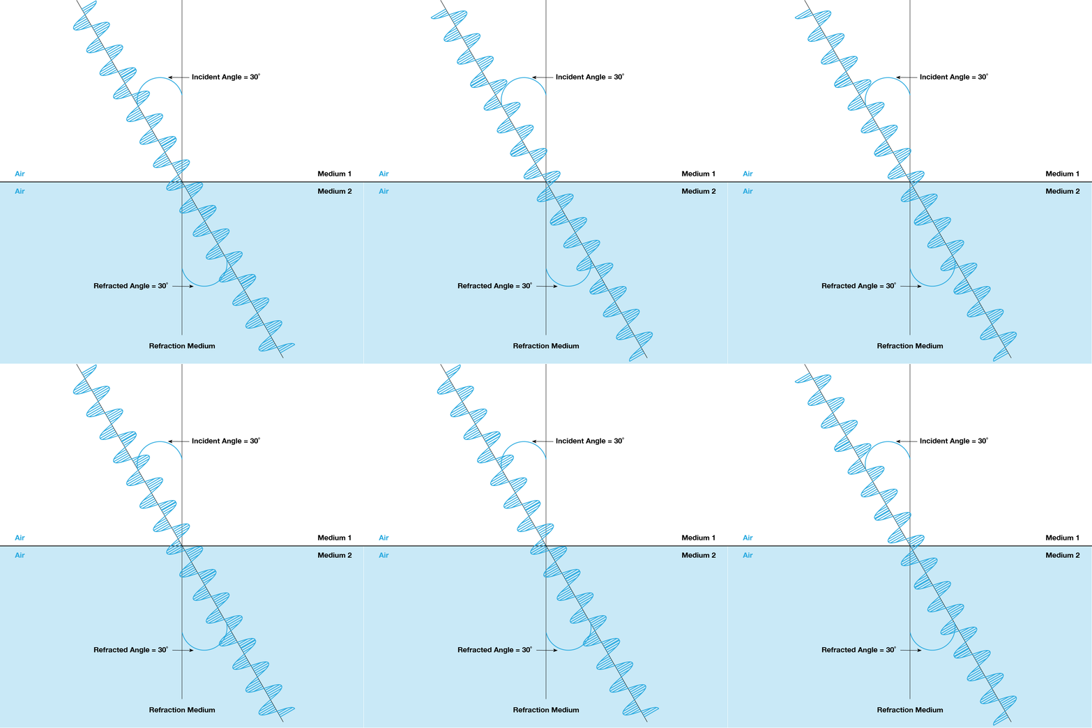
Air, the rate is 1.003
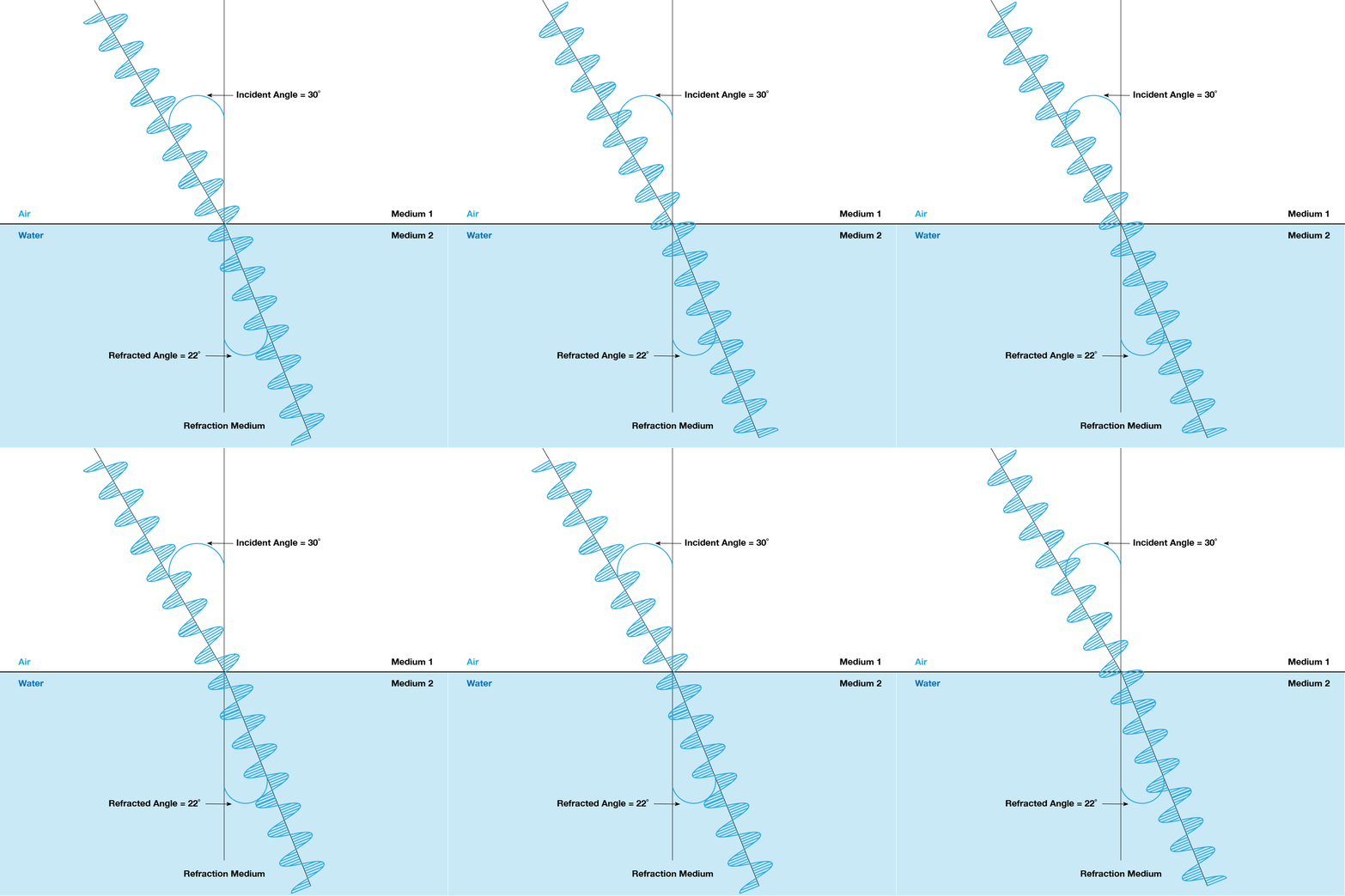
Water, the rate is 1.33
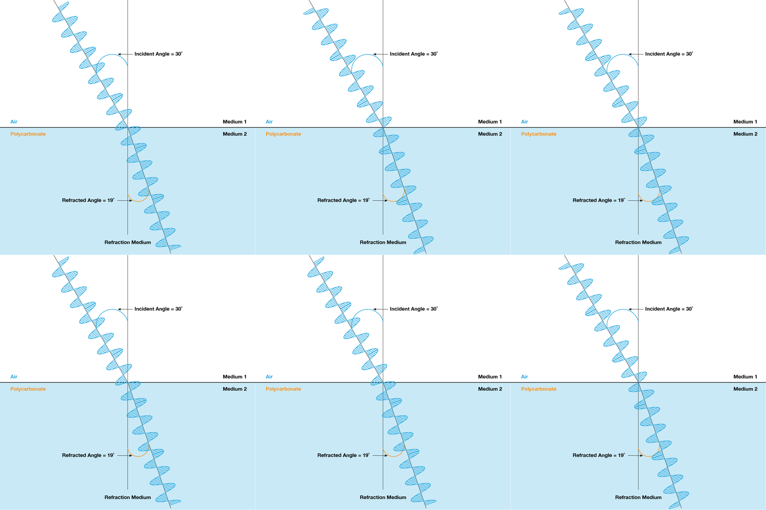
Acrylic, which is what most light pipes are made of — it’s ~1.49.
Refractive Index isn’t the only number that needs to come into play when it comes to how a surface affects light.
There’s also total internal reflection (TIR), which is the angle at which light is reflected when none of it shines through to a surface exit, instead it is reflected from one surface to another where it is visible.
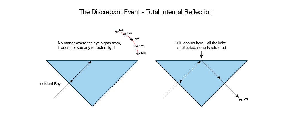
Source: https://www.physicsclassroom.com/class/refrn/Lesson-3/Total-Internal-Reflection
TIR is a phenomenon that occurs when the angle of incidence is greater than a certain limiting angle, referred to as the critical angle.

Why does TIR matter in light pipe design?
Often, light pipes are used to guide light around corners. To help ensure that the light bounces at the critical angle and travels to the endpoint with maximum effectiveness, understanding the critical angle of various materials is essential.
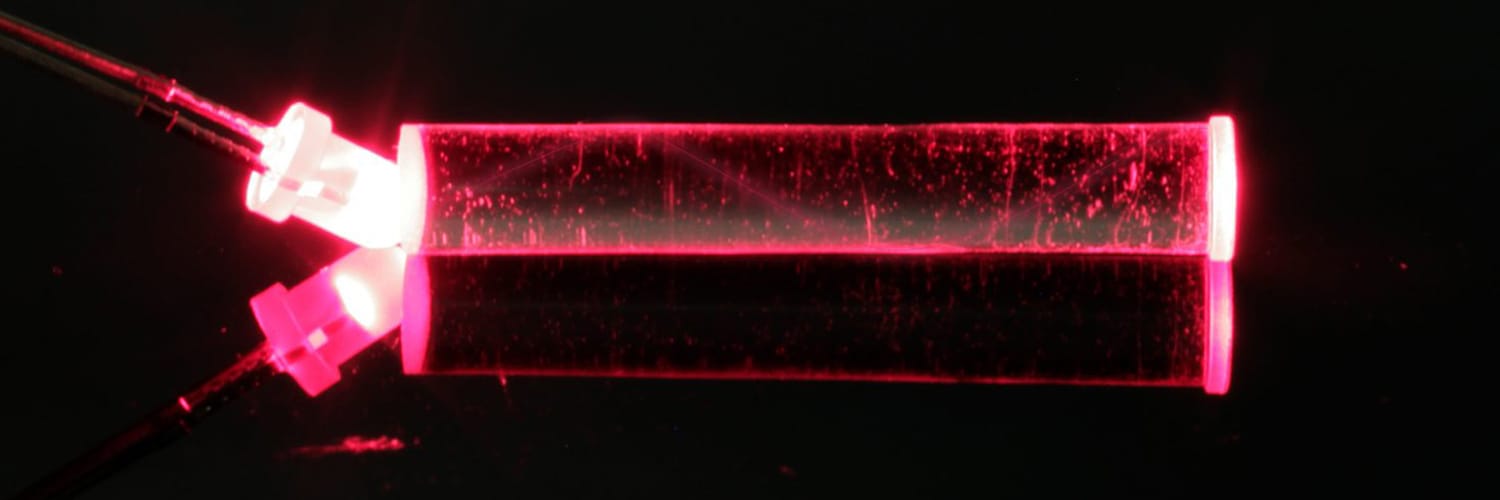
For clear polycarbonate, the critical angle is 39, and for acrylic, it’s 42.
Understanding how the light reacts in different scenarios will lead to better, more optimized light pipe performance.
For example, when using a right-angle light pipe, here’s how TIR would affect the specifications:

When designing light pipes, most people assume light behaves like electric current and ignore TIR.
Because light has unique properties, designing a light pipe like the right-angle illustration shown above will result in significant light loss at the TIR. To avoid light loss, incorporate the critical angle to create a geometry to guide the light around the critical angle without having the light escape. This concept also applies to light pipes with round corners (or any geometry your design includes).
Two types of light pipes are commonly used: rigid and flexible pipes.

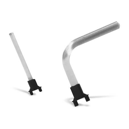
A rigid light pipe is designed to carry light shorter distances in moderate to high vibration conditions and in damp or dusty environments. Rigid light pipes are available in many configurations including vertical, right angle and multi-levels and are designed for distances up to 3 inches. A rigid light pipe is constructed from polycarbonate.
Rigid light pipes are available in numerous configurations, including straight, right angle, single-unit, or multiple-unit, stacked or vertical arrangements Rigid light pipes with an IP67-rated heavy-duty threaded retention provide maximum protection against liquid and dust incursion. Complete solutions are available that include the light pipe, the LED, and a surface-mount adapter.
Overall, rigid light pipes are an economical way to move light from an LED to the indication area on the front panel when direct access is available.

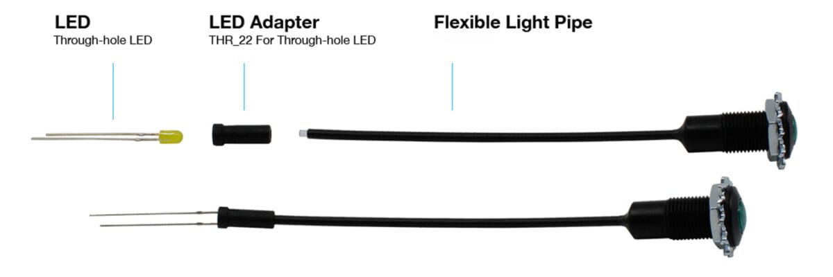
A flexible light pipe is preferred when light must be moved over longer distances or around obstacles between the LED and a front panel or other display location. A flexible light pipe assembly consists of an adapter, which provides less to no light bleed, and a flexible optical fiber with a lens cap. Flexible light pipes are immune to electromagnetic interference (EMI) and do not conduct or transfer electrostatic discharge (ESD) pulses.
Flexible light pipes are more complex and cost more than rigid light pipes; they solve accessibility challenges for engineers by giving them the flexibility to bypass components on the printed circuit board (PCB) that prevent a straight-line access to the indication area on the front panel.
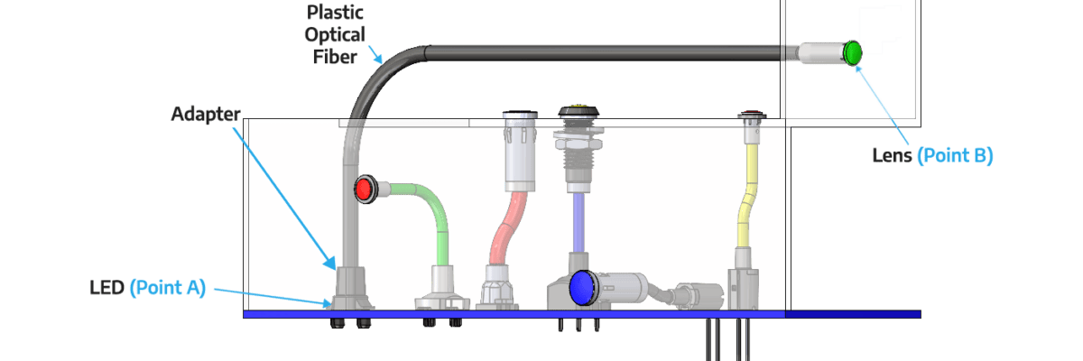
Figure 5 shows the various parts of a flexible light pipe design. The components consist of the LED at point A; a SMD-22 adapter that ensures no light bleeds into an adjacent pipe; a plastic optical fiber (POF); and a lens cap at point B that is bonded to the POF.
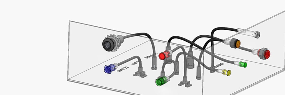
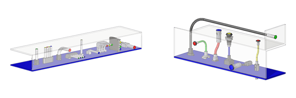
Flexible light pipes make it easy to add additional indicators or replace a damaged assembly because the lens cap at point B can be up to 330 feet from the LED light source at point A. The light pipe and lens need far less room near the panel face than the LED and its circuitry. If a human-factors engineer finds another indicator is necessary and space is an issue, a large redesign can be avoided by adding another indicator with a flexible adapter routed from another LED that may be in a completely different location from the first LED. The coupling of design time and design space radically improve cost concerns in a variety of industries and applications. Five different POF jacket colors improve installation and visual identification in the field by technicians, as well as clarify references in user manuals.
Rigid and flexible light pipes offer you two distinct options. Each one has advantages and disadvantages. Here are some guidelines to help you make the right choice.
Consider a Rigid light pipe if these parameters apply to your project:
- Light only needs to travel a short distance
- Low cost is a top priority
- The printed circuit board is located close to the front panel with simple access available
Look towards using a Flexible light pipe if:
- The light must travel a long distance
- The design of the equipment does not allow for a direct path from the LED to the display lens
- There is a possibility that additional indicators may need to be added later
- The human factors design is not yet finalized
- The LED output must travel through a high-EMI environment before reaching the lens cap
The design engineer must pay close attention to the pairing of the light pipe and the LED to minimize light loss and ensure best performance. The LED must be effectively matched to the entrance of the light pipe to allow for proper light capture with minimal light loss.
Of course, light pipe position can impact the light properties. To minimize light loss, a general rule is to use an LED with a narrow viewing angle of 160 degrees or less and position the light pipe and LED no more than 0.05” apart. There’s a little more to it than that to get the best product for your design. That’s where light simulations come in. Contact our team to run a simulation and determine the ideal light pipe for your design. And, don’t forget the constraints you may have based on the type of light pipe you use: Rigid light pipe design constraints Can’t bend Length limits: Press fit: 1.20” Custom: 1.5” Standard: up to 2” with shorter versions available Flexible light pipe design constraints Bends up to 30 degrees
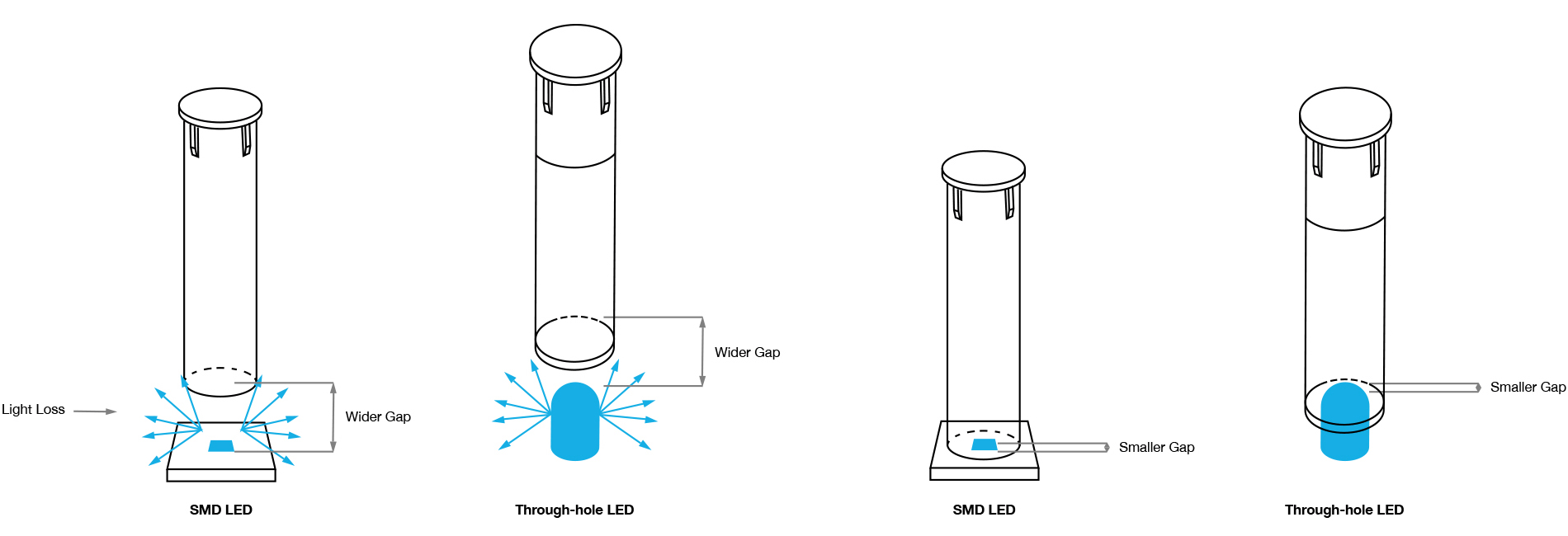
Light pipe position
Light bleed occurs when light from the LED can be visible around the LED and light pipe area. Light bleed causes false-readings, muted and blended colors, crosstalk between adjacent light pipes, and unwanted glow in the enclosure. When a rigid light pipe is located over the LED, it allows for a certain amount of light bleed at the base of the light pipe. A flexible light pipe is designed to provide less light bleed with a coated optical fiber and a light resistant black adapter.
The maximum flexibility occurs when the designer can choose between designing with individual components (LED and light pipe) or using a complete solution that includes both elements.
Light pipes are designed to carry light from Point A to Point B as effectively as possible.
Point A: Where the input or light source is located. In most cases, it’s the surface-mount (SMD) LED.
Point B: The exit surface, or where the end-user sees the light at the interface or indicator panel of the device.
Light loss, or light bleed, occurs when some of the light traveling from Point A to Point B escapes or shines elsewhere, so less light is available to shine at the exit point.
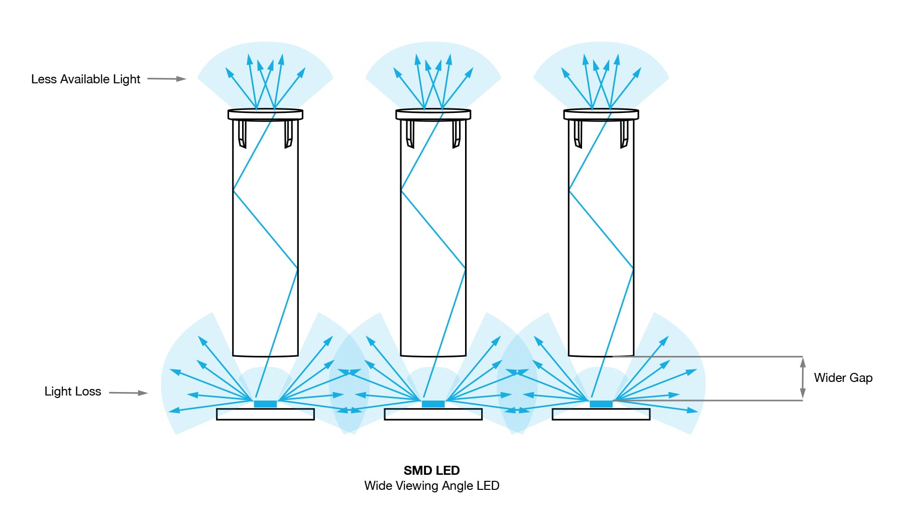
Light Loss
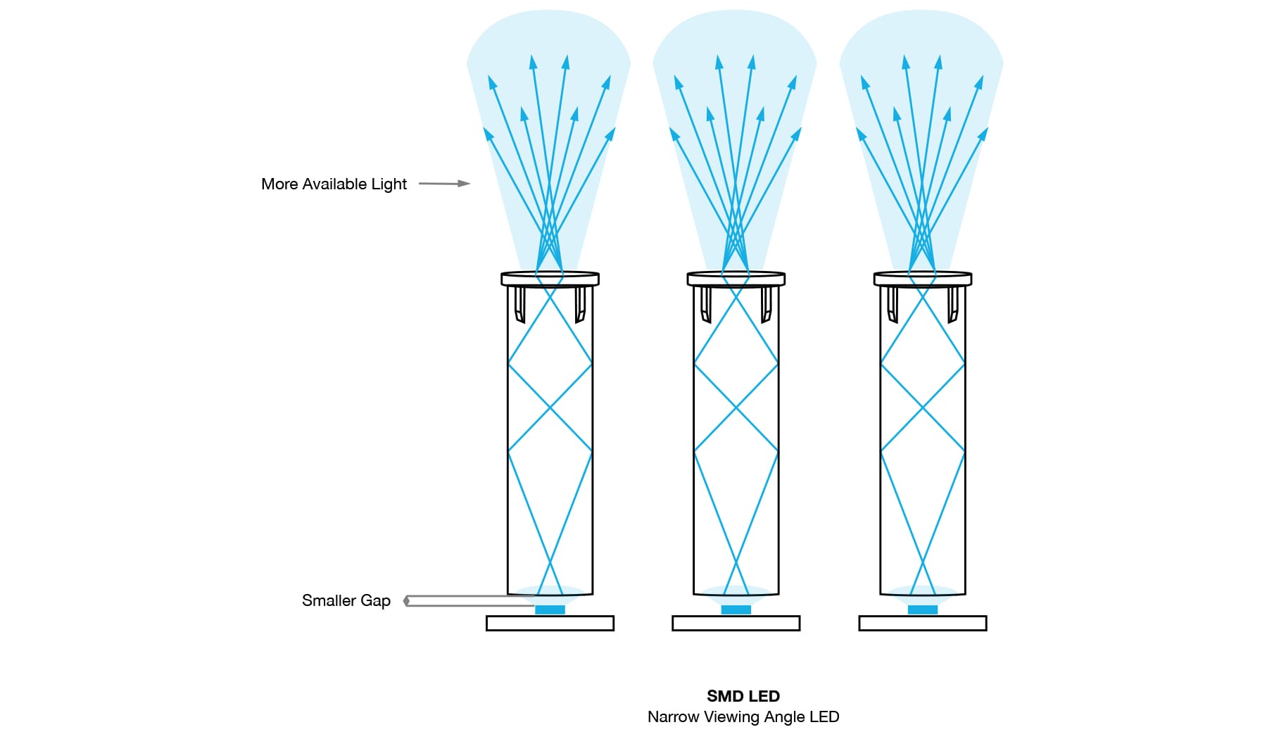
More Light
To minimize the amount of light loss, designers can use an LED with a narrow viewing angle instead of one with a wide viewing angle to help close the distance between the light pipe and LED where light could escape. The wider the gap between the light pipe and the LED, the more room for light to escape before it enters the light pipe and travels to the exit point.
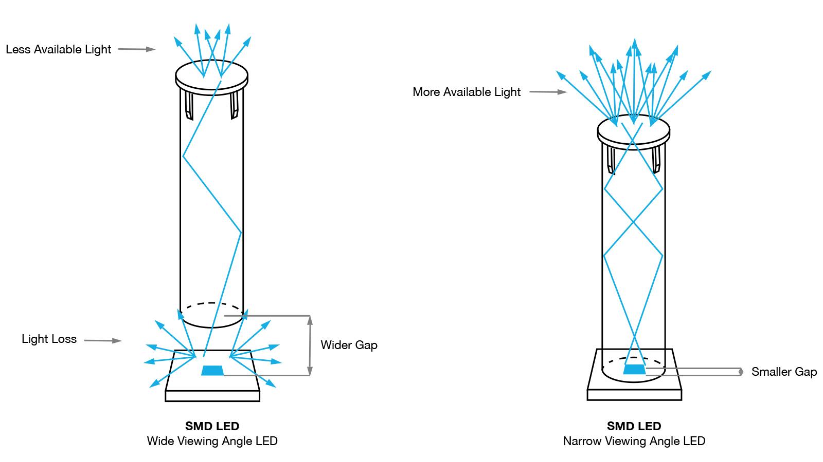
Note: there will always be some level of light that gets lost traveling from where the LED is located and the exit point where the end-user sees the light.
No matter which type of light pipe is chosen, there are multiple options available to optimize the design.
A surface mount (SMD) LED is mounted on the surface of the PCB and does not require holes. Through-hole LEDs are mounted by inserting leads through the PCB and soldering to provide a stronger connection between layers, which also can withstand some environmental stress conditions. An SMD LED tends to be smaller and brighter than the through-hole equivalent. Both through-hole and SMD LEDs are available in a wide range of sizes, colors, luminosities and lower power wattage.
LED color. SMD LEDs and through-hole are available in a wide range of single colors. SMD LEDs have additional options, including white or single, bi-color and tri-color, in an array of color configurations. Light pipe adapters are available for use with both types of LEDs. In addition, the designer can choose an adapter with a built-in LED or one intended for use with a separate LED.
LED size. Surface mount LED are based on industry standard sizes and through-hole LEDs are sized in millimeters (1.8mm, 3mm, 5mm). For example, an 0402 package (SM0402) is based on approximate dimensions (length × width) at roughly 0.4mm long by 0.2mm wide.
LED intensity. The light output (brightness intensity) of SMD LEDs and through-hole is commonly measured in millicandelas (mcd) or lumens (lm). The higher the mcd or lm rating, the brighter the light intensity.
The lens is mounted or molded on the end of the light pipe; it provides a convenient visual indicator and also protects the light pipe from mechanical disturbance. Some lens parameters are:
Lens profile. A Fresnel lens is designed to focus light and provides reduced shadowing and glare, and a wide viewing angle. A simple flat lens profile or dome lens is also used for increased viewing angle.
Lens color. Diffused, smoked, and color (blue, black, green, gray, red, yellow) lens options are available, depending on model.
Lens size and shape. A variety of lens sizes is available, including diameters of 2mm, 3mm, 4mm and 5mm. Round, oval, and rectangular shapes are available.
Applications in many industries must operate in harsh environments where it is critical that the lens cap appropriately sealed against the elements with the appropriate IP rating. The IP rating of a lens cap indicates the level of protection it provides against the incursion of solids, including dust, and liquids, including moisture or water. An IP rating is expressed in the form “IPXY”, where X and Y are numeric values.
The first digit in an IP rating indicates the level of ingress protection against solid objects: from IP0x (no protection) to IP6x (complete protection against dust). The second digit refers to protection from liquids: from IPx0 (no protection) to IPx9 (protection against water jets).
A light pipe design includes more than the LED, pipe, and lens. Additional components are needed to make up a complete system, and there are several options for each one.
There are various mounting options for light pipes depending on your application and manufacturing requirements.
If flexible and rigid were the only options, your options might be limited. Light pipes are designed to accommodate a wide range of mounting types.
In addition to the rigid vs. flexible decision, there are several other considerations when choosing a light pipe for your design. Your power source and overall design footprint can dictate which mounting type you should use with your light pipe.
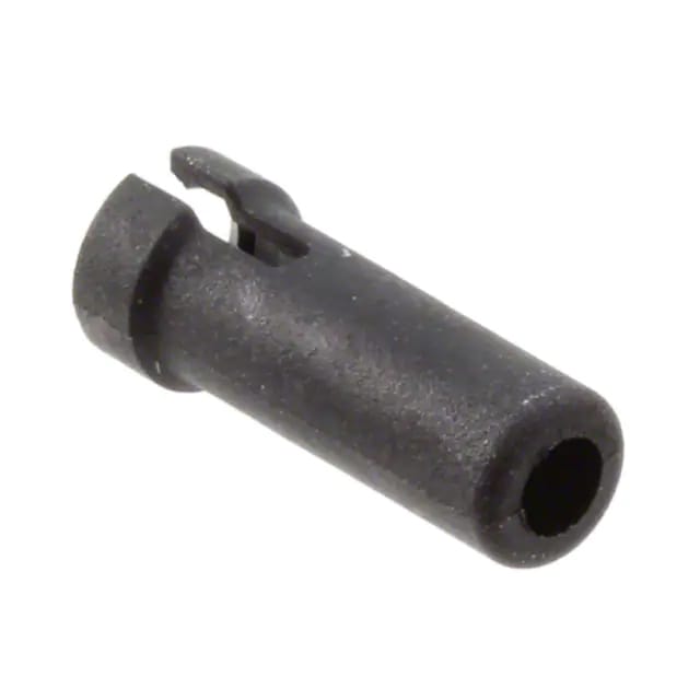
THR-22
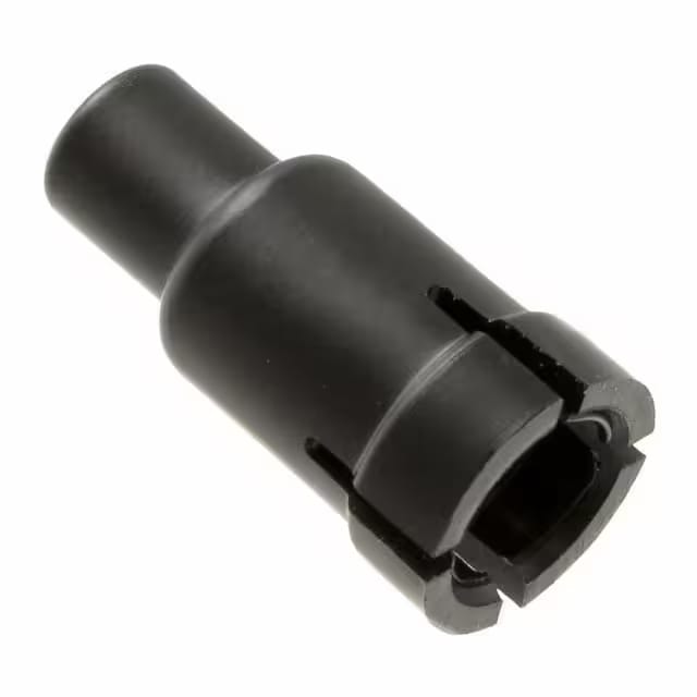
THR-5-22
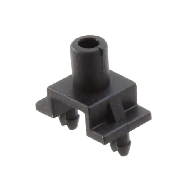
SMD-22
All Langier News:
Read Moreelectronica 2024 Hall-Stand No.: A2 160 November 12-15, 2024 Tr...

 English
 简体中文
简体中文