EN
EN

Capacitors are essential in modern technology and are used in almost every electronic device. According to Precedence Research, the global capacitor market is expected to reach $61.83 billion by 2032. Capacitors come in various shapes and sizes, each with its specific use. Additionally, they have a variety of symbols; each capacitor symbol represents different meanings and properties.
So, if you are working in electronics, you must understand the meaning of each symbol. They provide valuable information about the type of capacitor, its capacitance, voltage rating, and other essential details. To know more about a capacitor symbol, its meaning, and how to decide it, let’s delve into the details!
What is a Capacitor?
A capacitor is an electronic component widely used in various electrical and electronic circuits. It is designed to store and release electrical energy, acting as a temporary reservoir or “energy buffer” within a circuit. Compared to a typical battery, a capacitor can store very small amounts of energy, such as 10,000 times smaller, which is still useful for many devices and circuits. Here’s the typical structure of a capacitor:
- It comprises two conductive plates separated by an insulating material known as the dielectric.
- The conductive plates are usually made of metal, such as aluminum or tantalum.
- While the dielectric can be made of various materials, including ceramic, paper, plastic, or electrolytes.
How Capacitor Works?
As we all know, metals are made of positively and negatively charged particles which make them neutral. However, when an electric field is applied, the electrons from the positive plate or side will start moving toward the negative plate. However, the dielectric between both plates doesn’t allow the electrons to pass through, resulting in electron accumulation on one plate.
The capacitor stores electrical energy in the form of the accumulated charge on its plates. The amount of charge stored is directly proportional to the applied voltage and the capacitance of the capacitor. The equation is given as follows:
- Q = CV relates the charge (Q) stored in the capacitor to the capacitance (C) and voltage (V) applied.
When the capacitor is connected to a circuit, such as a load or another component, it can release the stored energy. This is known as discharging.
Applications
Here are some applications of a capacitor:
- Energy storage in power supply circuits to provide a stable source of energy.
- Coupling and decoupling capacitors block DC and allow AC signals to pass.
- Filtering and smoothing of electrical signals to remove noise and ripples.
- Motor starting and phase-shifting in electric motors and HVAC systems.
Capacitor Types
Before digging into the details of capacitor symbols, we should first look at the different capacitor types. Here are a few of them:
-
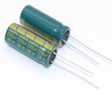
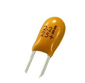
Electrolytic Capacitors
Electrolytic capacitors are polarized capacitors that use an oxide as the dielectric material. They have high capacitance values and are typically used in applications that require high capacitance and voltage ratings. In this, a thin metal film layer is used as the first electrode, while the second electrode (cathode) is a semi-liquid electrolyte. Here are the applications of electrolytic capacitors:
- They are used in audio circuits for coupling, decoupling, and filtering applications.
- Electrolytic capacitors are commonly used in power supplies to smooth out voltage fluctuations and reduce ripple.
-
Film Capacitors
Film capacitors are non-polarized capacitors that use a thin plastic film as the dielectric material. Typically, a film capacitor is made using the film drawing process. The film is manufactured and metalized depending on the properties of the capacitors.
They are available in various types, including polyester (Mylar), polypropylene, polycarbonate, and polyphenylene sulfide (PPS) film capacitors. The significant difference between each type of dielectric material used between the plates. Here are some of the applications of film capacitors:
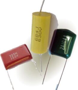
- They are used in single-phase AC motors to improve efficiency and provide a phase shift.
- Commonly used in the aerospace and military industry for manufacturing various devices.
-
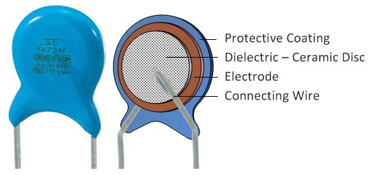
Ceramic Capacitors
These are the ones that use ceramic material as a dielectric. They have various shapes and sizes, including ceramic tubular and barrier layer capacitors. The two most common types are the multilayer ceramic capacitor (MLCC) and ceramic disc capacitor. MLCCs, made through surface-mounted technology, are particularly popular due to their compact size.
On the other hand, ceramic disc capacitors are coated with silver contacts on both sides. These capacitors boast a high dielectric constant (High-K), offering substantial capacitance. Here are some applications of ceramic capacitors:
- They are employed in timing circuits, such as oscillators and resonators.
- Ceramic capacitors are used for filtering and coupling applications in audio circuits, RF circuits, and power supplies.
-
Tantalum Capacitors
Tantalum capacitors are electrolytic capacitors and consist of tantalum metal serving as the anode. They feature a thin oxide layer acting as the dielectric, surrounded by a conductive cathode. The use of tantalum allows for a highly efficient dielectric layer. Therefore, you will see a higher capacitance value per volume and superior frequency characteristics than other capacitor types.
Furthermore, tantalum capacitors exhibit excellent long-term stability and efficiency. These capacitors are typically polarized, meaning they can only be connected to a DC power source while maintaining the correct terminal polarity. Here are some critical applications of tantalum capacitors:
- Tantalum capacitors are used in various consumer electronic devices, such as smartphones, laptops, and digital cameras, for power supply decoupling and filtering.
- They are employed in telecommunications equipment, including routers, switches, and base stations, for voltage regulation and noise suppression.
-
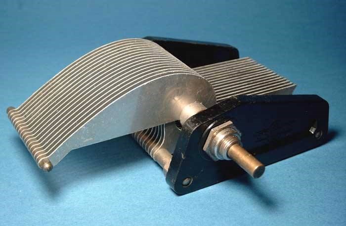
Variable Capacitors
Typically, a variable capacitor has a varying capacitance that can be manually adjusted. The capacitor consists of two plates; one is stationary, while the other is movable. This configuration allows the capacitor to provide a capacitance range from 10 pF to 500 picofarads. Some common types of variable capacitors include trimmers and turning capacitors. Here are some applications of the variable capacitors:
- They are used in oscillators, tuners, filters, etc.
- Applicable in medical devices like MRI and NMR scanners to generate accurate results.
Capacitor Symbols
Now that you know the many types of capacitors, let’s discuss what a capacitor symbol is and its types!
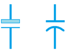
The symbol generally used to represent a capacitor in electronic circuit diagrams combines two parallel lines with a gap between them. It varies according to the type;
1. Fixed Capacitor Symbol

The symbol of a fixed capacitor is typically represented as two parallel horizontal lines with a space between them.
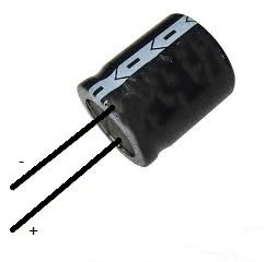
2. Polarized Capacitor Symbol
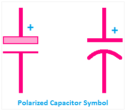
The symbol of a polarized capacitor includes a straight line and a curved line. The curved line represents the negative terminal, often indicated with a minus (-) sign or a specific marking on the capacitor. The straight line represents the positive terminal, typically the longer lead on the physical capacitor.
3. Variable Capacitor Symbol

The symbol for a variable capacitor in circuit diagrams is typically represented as two parallel lines with an arrow indicating the adjustable portion.
4. Electrolytic Capacitor Symbol
The symbol for an electrolytic capacitor is either two parallel lines or a straight line and a curved as shown in the image
5. Bipolar Capacitor Symbol

The symbol for a bipolar capacitor resembles a non-polar capacitor symbol in structure and can be connected to a circuit in any direction.
6. Trimmer Capacitor Symbol

A commonly used symbol for a trimmer capacitor is two parallel lines with a diagonal line in between, indicating the adjustable nature of the capacitor.
7. Feed Through Capacitor Symbol

The symbol for a feedthrough capacitor is usually represented as a capacitor with a straight line passing through it. This line represents the electrical connection or feedthrough between the two sides of the capacitor.
8. Voltage-Dependent Capacitor Symbol

One commonly used symbol for a voltage-dependent capacitor is a regular capacitor symbol with an arrow or a curved line pointing into it, indicating the dependency on the applied voltage.
9. Temperature-Dependent Capacitor Symbol

You can represent the temperature-dependent capacitor symbol by adding a temperature coefficient symbol to the regular capacitor symbol. The temperature coefficient represents the change in capacitance with respect to temperature.
How to Read Capacitor Symbols?
You should be able to read a capacitor symbol to understand electronic circuit diagrams and schematics. Here’s the procedure to do so:
1. Know the Units of Measurement
Capacitance is measured in Farads (F), but in practice, capacitors are typically rated in smaller units such as microfarads (μF), nanofarads (nF), or picofarads (pF). Familiarize yourself with these units to interpret the values correctly.
2. Find the Capacitance
Numerical digits represent the capacitance value on the capacitor symbol. Look for a number that indicates the capacitance value. The number may be followed by a letter code indicating the unit of measurement.
3. Search for Tolerance Value
All capacitors have a tolerance that specifies the maximum allowable deviation from the stated capacitance value. This tolerance is represented by a percentage or a code on the symbol. The tolerance values can be anything, such as ±5%, ±10%, ±20%, or more. For instance, If you find “104K” on the symbol, the letter “K” represents a tolerance of ±10%.
4. Find the Voltage Rating
Capacitors also have a voltage rating, indicating the maximum voltage they can safely handle. The voltage rating is usually represented as a number followed by a unit such as volts (V) or kilovolts (kV). For instance, If you see “25V” on the symbol, the capacitor can handle a maximum voltage of 25 volts.
5. Look for a Positive or Negative Sign
Some capacitors, particularly polarized electrolytic and tantalum capacitors, have a polarity. They must be connected in the correct direction, or they may fail or even explode. The positive and negative terminals are indicated on the symbol using different markings, such as a plus sign (+) or a minus sign (-).
FAQs
1. Why is the Capacitor Symbol important in Circuit Diagrams?
The capacitor symbol is vital in circuit diagrams as it represents the location of a component called a capacitor in a circuit. Capacitors typically store and release electrical energy and are an important circuit part.
2. Why are there different Symbols for Different Types of Capacitors?
Every capacitor has a different capacitance and voltage rating, so using different symbols for different types of capacitors is essential. These different symbols allow engineers and technicians to understand the type of circuit being used in a device.
3. Can I replace One type of Capacitor with another in a Circuit?
Yes, you can replace one type of capacitor with another in a circuit, but remember to make sure the capacitor you use has a higher voltage rating than the previous one, or there may be some complications. Also, remember that each capacitor type has different applications and manufacturing materials, so replacing one with the other can affect the overall working of the circuit.
4. What is the difference between Polarized and Non-polarized Circuit Capacitors?
Polarized circuit capacitors are polar sensitive and can only be connected in a particular direction in a circuit. In contrast, a non-polarized capacitor is one that has no polarity and can be connected in any direction in a circuit.
5. How can I tell if Capacitor is Polarized or Non-polarized based on its Symbol?
A polarized capacitor typically has a positive terminal represented by “+” and a negative terminal represented by “-” This indicates the capacitor is polarized, and you need to be careful about direction when connecting it to a circuit. In contrast, a non-polarized capacitor does not have any specific polarity markings and can be connected in any direction.
6. How can I determine the value of a Capacitor based on its Symbol?
You can easily determine the value of a capacitor using a digital multimeter or by reading the color codes printed on the capacitor.
7. How is the Capacitance value indicated in a Capacitor Symbol?
The capacitance value on a capacitor symbol is indicated by a numerical value followed by the SI unit of capacitance, which is Farad. However, due to the small capacitance values of some capacitors, these values can be micro or Pico Farad.
Conclusion
A capacitor is used in almost all electronic devices and has different types. These include variable, tantalum, film, etc., and all these symbols are represented by unique term symbols. A term symbol helps engineers and technicians identify the type of capacitor used in a circuit and its application. You can read the term symbols easily if you know the capacitance measurement unit, how to find voltage rating and other things.
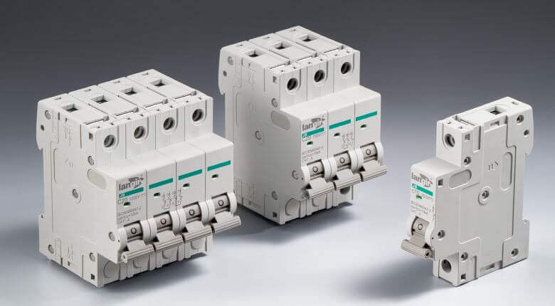
So, if you are looking for high-quality capacitors and other DC circuit products, Langir is your one-stop shop. With our years of experience, we ensure our customers get the latest and most reliable products. So, contact us and book your orders now!
All Langir News:
Read More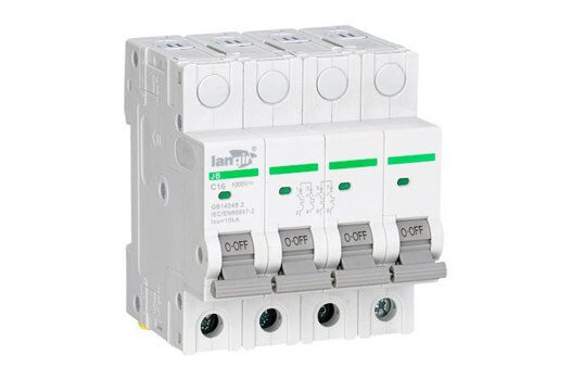
Unravel the myth of directionality in DC circuit breakers. This guide dispels confusion, helping readers understand their funct...
Unexpected power solutions await! Wire size details for ACS 300A DC circuit breakers ensure safety and efficiency in any setup....
When a DC circuit breaker is hooked up backwards, it can lead to unexpected outages and potential hazards. Understanding this i...
Unlock the secrets of DC circuit breaker calculations for 24V systems. Learn to simplify your projects and enhance safety with ...