All LEDs require some form of current limiting. Connecting an LED directly to the power supply will burn it out in a heartbeat. Overdriving, even briefly, will significantly reduce it’s life and light output.
Fortunately, driving a single or a string of low current (20-30 mA) LEDs is a simple task – adding a small resistor in series is the easiest and cheapest way to limit the current. Keep in mind however, that high current (above a few hundreds of mA) LEDs are tougher to drive, and while they can be operated with a series resistor, to minimize power loss and ensure reliability, it’s advisable to use a more expensive switching current regulator.
Our LED calculator will help you determine the value of the current limiting series resistor when driving a single or an array of low-current LEDs. To get started, input the required values and hit the “Calculate” button.
The program will draw a small schematic, display the calculated resistance and will tell you the value and color code of the nearest lower and higher standard resistor. It will calculate the power dissipated by the resistor and LED(s), the recommended resistor Wattage, the total power consumed by the circuit and the efficiency of the design (Power consumed by the LED(s) / Total circuit power consumption) x 100).
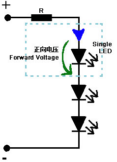
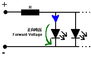
Supply voltage: Type in a voltage greater than the LED voltage drop for a single LED circuit and parallel connection or the sum of all voltage drops when connecting multiple LEDs in series.
LED current: Type in the single LED current in milliamperes. Common 3 mm and 5 mm LEDs usually operate in the range of 10-30 milliamps, but power LEDs used in lighting and automotive applications can have current requirements above 200 mA. A current of 20 mA is usually a safe value if you don’t have access to the component’s datasheet.
LED color and Voltage drop: Select the color of your LED. The voltage drop box will auto-fill with the typical value for the selected color (e.g. 2V for a standard red LED; 3.6V for a white LED used in lighting, stroboscope, etc; 1.7V for an infrared LED used in remote controls, etc.). However, the voltage drop varies greatly between different types of LEDs and also changes slightly with the current, so please change it if you know the correct value for your component.
Number of LEDs: Select the number of LEDs you want to use in your circuit. For multiple LEDs a second drop-down will appear where you can select either a series or parallel connection.
Note: You should avoid connecting LEDs in parallel with just one resistor shared between them. Identical LEDs can be successfully connected in parallel, but each LED may have a slightly different voltage drop, and the brightness of the LEDs will differ. If you want to connect the LEDs in parallel each one should have its own resistor. Calculate the value for a single LED and connect all the LED-resistor pairs in parallel.
Resistor precision: select the desired standard resistor precision: 10% , 5%, 2% or 1%. Use our resistor color code calculator to find out the color bands for different (20%, 0.5%…) precision resistors.
 English
 简体中文
简体中文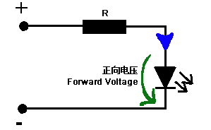
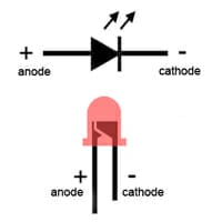 An LED has two leads: a positive (anode) and a negative (cathode). On schematic diagrams, its symbol is similar to the simple diode, with two arrows pointing outwards. The anode (+) is marked with a triangle and the cathode (-) with a line. Sometimes you’ll find additional labels: A or + for anode and K or – for cathode.