RECOMMENDED SOLDERING PROFILES
Soldering Profiles
Soldering conditions are affected by mounting and PCB parameters. Please take these factors into account when using these solder profiles. These are recommendations only and no guarantees are implied by them.
COMPONENT TESTING AFTER REFLOW/REWORK FOR MLCC’S:
All component testing after reflow/rework should be performed after ≥ 24hrs to ensure accurate capacitance value measurements. Capacitors should be cooled at room temperature for a minimum of 24 hours to allow the ceramic material to reset (age).
MSL LEVEL
MSL (Moisture Sensitivity Level) is 1
RECOMMENDED SOLDERING PROFILES (REFERENCE)
Normally, the user adopts the method and the process best suited for their own application, taking into account such factors as type, the manufacturer’s recommendation on soldering test and proximity of components on the PCB, equipment, etc.
The same criteria are applicable for lead (Pb)-free terminals. Obviously, the standards should be pertinent to lead (Pb)-free mounting pastes.
The eutectic temperature of the plating alloy determines the minimum limits of the soldering process temperature.
The minimum soldering temperature range should be at least 5 °C to 10 °C higher than the eutectic temperature of the plating alloy (per technical literature).
The devices must be held at the peak soldering temperature long enough to ensure the proper wetting of the solder connections. However, keeping the peak soldering time to a minimum to avoid the possibility of damage to the devices is recommended (per technical literature).
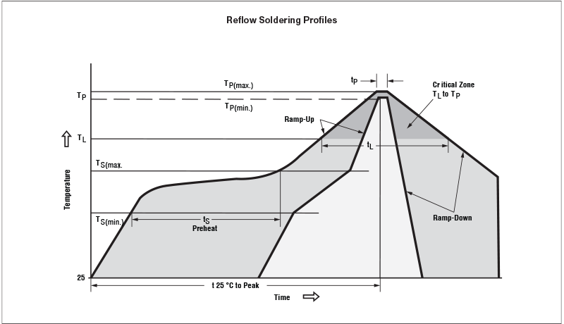
| Classification of Reflow Profiles | ||
| Profile Feature | Sn – Pb Eutectic Assembly | Lead (Pb)-Free Assembly
(e.g. SnAgCu) |
| Average ramp-up rate (T(Smax.) to TP) | 3 °C/s maximum | |
Preheat
|
100ºC
150ºC 60 s to 120 s |
150ºC
200ºC 60 s to 180 s |
Time maintained above
|
183ºC
60 s to 150 s |
217ºC
60 s to 150 s |
| Minimum peak temperature (TP(min.)) | 215ºC | 235ºC |
| Recommended peak temperature (TP) | 235ºC | 250ºC |
| Maximum peak temperature (TP(max.)) | 260ºC | 260ºC |
| Time within 5°C of actual peak temperature (tP) | 10 s to 40 s | 20 s to 40 s |
| Ramp-down rate | 6ºC/s maximum | 6ºC/s maximum |
| Time 25°C to peak temperature | 6 min maximum | 8 min maximum |
Hand Soldering and Temperatures
Notes
- This document should serve as recommendation only. Other parameters may also affect soldering, so these profiles do not guarantee absolute success.
- Soldering profile should be determined by the manufacturer of the solder paste, providing there is no contradiction with the recommendations in this document.
| Soldering Iron Recommended Specifications | |||||||
| Soldering Temp (°C) | Preheat Temp (°C) (component or board) |
Preheat Time (sec) | Max. Variation Temp (°C) | Max. Soldering Time (sec) | Wattage | Tip Diameter | Soldering Time |
| 280~300 | ≥150°C | ≥60 seconds | △T≤130 | ≤5 seconds | 30W max. | 3mm Max. | 2~3 sec. max. |

 English
 简体中文
简体中文
