 EN
EN
Engineers require precise capacitance determination the instant a switch closes. Accurate measurement of a capacitor’s charge storage capacity at switch closure is critical for designing robust capacitive switches and reliable RC networks. This guide defines capacitance and its relationship to switching events, analyzes capacitor behavior at t=0+, derives essential equivalent capacitance formulas, explores RC transient response, explains capacitive touch sensing principles, and highlights the industrial significance of these insights.
Capacitance Defined: Its Relationship to Switch Closure
Capacitance quantifies a component’s electric charge storage per volt. Closing a switch instantaneously integrates the capacitor into a circuit. Comprehending this relationship is fundamental for predicting initial voltages, currents, and sensing behavior upon capacitive switch activation.
Get a quote for custom capacitive switches from Langir
Capacitance in Electrical Circuits
Capacitance measures a component’s charge-storage capacity, defined by C = Q/V, where Q represents stored charge and V is voltage. Within circuits, capacitors facilitate AC signal passage while blocking steady DC post-charging, thereby shaping frequency response and transient dynamics critical for sensing and timing applications.
Capacitance and Circuit Dynamics
Capacitance quantifies a component’s capacity to store electrical charge, defined as the ratio of charge to voltage. In circuit design, capacitors are instrumental in shaping frequency response and transient dynamics, which is essential for precise sensing and timing applications.
Serway, R. A., & Jewett, J. W. Physics for Scientists and Engineers (2018)
This foundational definition is critical for comprehending capacitor behavior in circuits, particularly concerning switching events.
This fundamental definition directly informs how switch actuation reconfigures a capacitor’s function within a circuit.
Impact of Switch Closure on Capacitance
Switch closure abruptly integrates or isolates capacitors within a circuit, instantaneously modifying total capacitance and impedance. At t=0+, the reconfigured network’s capacitance dictates the immediate charge distribution and establishes initial conditions for subsequent voltage and current transients.
This switch-induced capacitance alteration enables predictable transient response and enhanced sensing accuracy.
Role of the Electric Field in Capacitive Sensing
A capacitor’s electric field extends between its conductive plates. Any disturbance, such as a human finger or conductive object, alters these field lines and consequently the effective capacitance. Capacitive switches precisely detect these field perturbations to initiate on/off events without mechanical components, significantly enhancing durability and hygiene.
Understanding field perturbation directly correlates theoretical principles with practical product performance and long-term reliability.
Analyzing Capacitor Behavior at Switch Closure
At the instant of switch closure (t=0+), a capacitor’s voltage and current adhere to fundamental circuit laws. Analyzing these initial conditions is essential for precise modeling of RC networks and for developing high-speed capacitive sensors.

Get a quote for custom capacitive switches from Langir
Initial Voltage Conditions of a Capacitor at t=0+
A capacitor’s voltage cannot change instantaneously. Therefore, at t=0+, the voltage remains equivalent to its pre-switch value. If the capacitor was initially uncharged (V₀ = 0), it effectively behaves as a short circuit at the moment of closure, preserving the continuity of electric potential.
This inherent voltage constraint is fundamental for deriving current transients immediately following a switching event.
Determining Initial Current Through a Capacitor at Switch Closure
The initial current i(0+) is determined by (V_source – V_C(0+))/R, in accordance with Kirchhoff’s laws, given that the capacitor presents as a short circuit at t=0+ when V_C(0+) is constant. A substantial inrush current flows into an uncharged capacitor until its voltage commences rising.
Quantifying this initial surge current is essential for robust circuit design and precise sensor calibration.
Capacitor Behavior as a Short Circuit Immediately After Switch Closure
At t=0+, the stored voltage is fixed, resulting in a finite time derivative of voltage (dV/dt). Consequently, the current i=C·dV/dt can be substantial. Effectively, the capacitor exhibits near-zero impedance, facilitating instantaneous current flow as if it were a direct conductor.
This short-circuit analogy simplifies initial transient analysis prior to the capacitor commencing its charging cycle.
Calculating Capacitance and Equivalent Capacitance in Switched Circuits
When switches reconfigure capacitor networks, it is imperative to compute the resultant single-value equivalent capacitance to accurately predict system behavior. These calculations are fundamental to the design of RC filters, precision timing circuits, and advanced capacitive touch sensors.
Prior to detailing the formulas, an overview of series versus parallel combinations is provided.
Understanding these relationships enables the immediate update of C_eq upon switch closure, facilitating instantaneous modeling of circuit dynamics.
Calculating Equivalent Capacitance for Series and Parallel Capacitors Upon Switch Closure
Upon switch closure, identify the series or parallel configuration of connected capacitors and apply the aforementioned formulas. For instance, closing a bypass switch that parallels two equal 1 μF capacitors results in an equivalent capacitance (C_eq) of 2 μF instantaneously.
This systematic approach ensures precise initial predictions for capacitor charging curves.
Formulas for Capacitance Determination in RC Circuits at Switch Closure
Key equations governing an RC network for t>0 include:
- V_C(t) = V_source·(1 – e^(–t/RC))
- i(t) = (V_source/R)·e^(–t/RC)
Here, R denotes the equivalent resistance, C represents the updated capacitance at switch closure, and t=0+ establishes the initial condition for these exponential functions.
Application of these equations enables the prediction of voltage rise and current decay over time.
Impact of Switch Position on Capacitance Measurement in Complex Circuits
Switch positions can reconfigure multi-capacitor arrays, thereby altering the equivalent capacitance (C_eq) and the time constant τ=R·C_eq. Comprehending how each switch state modifies network topology is critical for designing capacitive switches capable of adapting sensitivity or timing across various operating modes.
This dynamic tuning capability is invaluable for advanced industrial control systems.
Transient Response of an RC Circuit Upon Switch Closure
Get a quote for custom capacitive switches from Langir
RC Circuit Transient Response Analysis
The transient response in RC circuits characterizes the evolution of voltage and current over time, from the instant of switch closure until a steady state is achieved. The time constant, τ = R*C, is a critical parameter, as it dictates the circuit’s response speed, thereby influencing the capacitor’s charging and discharging dynamics.
Nilsson, J. W., & Riedel, S. A. Electric Circuits (2019)
A comprehensive understanding of transient response is essential for designing reliable capacitive switches and accurately predicting their performance across diverse applications.
Voltage Evolution in an RC Circuit Post-Switch Closure
Following closure, capacitor voltage adheres to , exhibiting an exponential rise toward the source voltage. The profile of this charging curve dictates sensor response speed and the precise moment a touch event is registered.
Analysis of this curve ensures consistent activation thresholds in practical applications.
Current Variation During RC Circuit Transient Response
Current commences at and decays exponentially as . The initial current surge charges the capacitor, succeeded by an exponentially diminishing flow. Engineers utilize this characteristic pattern for appropriate resistor sizing and to safeguard circuits against inrush currents.
A thorough understanding of current decay is crucial for preventing false triggers in capacitive switches.
The Time Constant: Influence on Capacitor Charging
The time constant τ = R·C_eq represents the duration required for voltage to attain approximately 63% of its final steady-state value. A smaller τ facilitates a faster response, whereas a larger τ provides greater smoothing of fluctuations. In capacitive switch applications, τ governs debounce time and touch-release delays.
Optimizing τ is a critical design parameter for achieving the optimal balance between sensitivity and stability.
Capacitive Switch Detection of Capacitance Changes Upon Activation
Capacitive switches detect minute shifts in electrode capacitance induced by touch or proximity. This non-mechanical detection method significantly enhances operational lifespan and hygiene in demanding industrial environments.
Get a quote for custom capacitive switches from Langir
Capacitive Sensing Principle in Push Button Switches
When a human finger approaches the switch surface, it establishes a virtual electrode, thereby increasing the total electrode capacitance. The switch’s integrated sensing circuit compares the baseline capacitance (C₀) to the altered value (C₁). When the differential capacitance (ΔC) exceeds a predefined threshold, the switch actuates.
This field-disruption methodology ensures reliable, wear-free actuation.
Signal Processing Interpretation of Capacitance Changes in Switch Circuits
A microcontroller or dedicated Application-Specific Integrated Circuit (ASIC) precisely measures the charge/discharge timing of the electrode network. It incorporates noise filtering, compensates for environmental factors such as temperature and humidity, and auto-calibrates baseline values to differentiate intentional activations from environmental drift.
Robust signal processing is foundational for achieving high-precision touch detection.
Materials and Components Influencing Capacitive Switch Sensitivity and Accuracy
Capacitive switch sensitivity is contingent upon electrode geometry, the dielectric constant of the overlay material, PCB layout, and the implementation of guard rings. Common overlay materials include glass, acrylic, PET, and stainless steel. Each material selection represents a balance among durability, optical clarity, and capacitive coupling strength.
Optimizing material configurations ensures consistent and reliable performance across diverse industrial applications.
Significance of Understanding Capacitance at Switch Closure for Industrial Capacitive Switch Applications
A comprehensive understanding of capacitance behavior at the moment of switch activation directly translates into the development of more durable, accurate, and responsive industrial control solutions. These insights are pivotal for enhancing product reliability and ensuring user satisfaction.
Enhancing Switch Durability and Performance Through Accurate Capacitance Measurement
Precise modeling of transient currents and capacitance shifts mitigates overstress on electronic components, reduces instances of false activations, and extends overall component lifespan. Optimally tuned designs achieve superior Mean Time Between Failures (MTBF) in demanding industrial environments.
Enhanced durability directly correlates with reduced maintenance expenditures.
Industrial Challenges Addressed by Capacitive Switch Technology
Capacitive switches exhibit inherent resistance to moisture, dust, and corrosive agents, eliminate the need for mechanical sealing, and provide full wash-down compatibility. Their non-mechanical actuation withstands extreme temperatures and vibration, effectively resolving reliability concerns in challenging industrial environments.
These inherent advantages facilitate new Human-Machine Interface (HMI) possibilities in sectors such as food processing, pharmaceuticals, and outdoor machinery.
Langir’s Customization of Capacitive Switches Based on Capacitance and Circuit Requirements
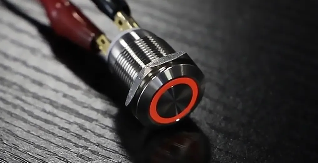
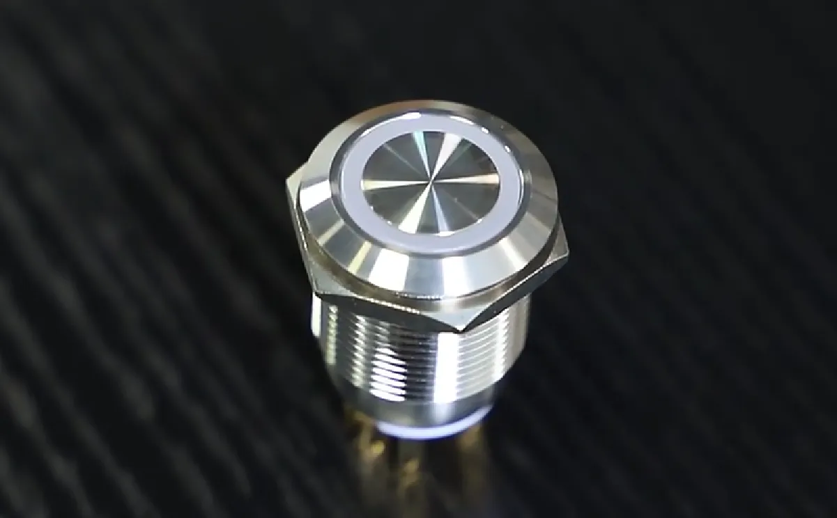
Langir customizes electrode geometry, overlay materials, and sensing electronics to precisely align with each client’s specific capacitance profile and transient behavior requirements. From robust 19 mm stainless-steel push buttons to bespoke touch panels, Langir offers comprehensive customization solutions. Request a custom capacitive switch quote to design switches that integrate seamlessly with your RC circuit specifications.
This precision-engineered approach ensures optimal sensitivity, extended longevity, and superior industrial readiness.
Capacitance at Switch Closure | FAQs
Capacitor Voltage Behavior Immediately After Switch Closure
Capacitor voltage maintains its pre-closure value, exhibiting no instantaneous change. It commences at V_C(0+) and subsequently follows the exponential charging or discharging curve dictated by the reconfigured circuit.
This characteristic behavior establishes precise initial conditions for comprehensive transient analysis.
Determining Current in an RC Circuit Upon Switch Closure
Calculate , considering the capacitor as a short circuit for the initial instant. For subsequent time points, utilize .
These formulas provide immediate, actionable results for circuit analysis.
Calculation of Equivalent Capacitance Upon Switch Closure
Identify parallel and series configurations of capacitors interconnected by the closed switch. Subsequently, apply for parallel arrangements and for series arrays.
This methodology is applicable irrespective of network complexity.
RC Circuit Transient Response: Significance and Implications
An RC transient characterizes the exponential evolution of voltage and current from t=0+ to a steady state, governed by the time constant τ = R·C_eq. Its significance lies in its direct influence on response speed, noise filtering capabilities, and sensor settling times within capacitive switch designs.
Accurate consideration of transient response ensures predictable and reliable operation under diverse real-world conditions.
Precise capacitance analysis at switch closure is foundational for developing dependable capacitive switch designs. By mastering initial conditions, equivalent capacitance calculations, and transient response, engineers can optimize sensitivity, mitigate false triggers, and extend product longevity in demanding industrial environments. Integrating these principles with Langir’s advanced customization capabilities yields push button switches that achieve an optimal balance of performance, durability, and user experience—ensuring every activation is precise and enduring.