EN
EN
Installing panel mount push button switches correctly ensures reliable machine control, safety compliance, and streamlined operations in any manufacturing environment. This guide delivers actionable instructions on wiring push buttons, choosing mounting locations, and meeting UL 508A and NEMA standards—all while highlighting how Langir supplies bulk push button switches and custom solutions. You will learn:
- What industrial push button switch types exist and how they work.
- Tools, materials, and safety gear required for installation.
- Best practices for panel mounting and physical alignment.
- Detailed wiring steps for common 2-pin, 4-pin, 5-pin, and illuminated switches.
- Testing procedures, troubleshooting tactics, and LED indicator fixes.
- Key industrial standards (UL 508A, NEMA, NFPA 70/79) that govern control panel installations.
- How Langir’s bulk inventory and customization services can support your next project.
By following this structured approach, you’ll minimize downtime, ensure compliance, and optimize control panel performance.
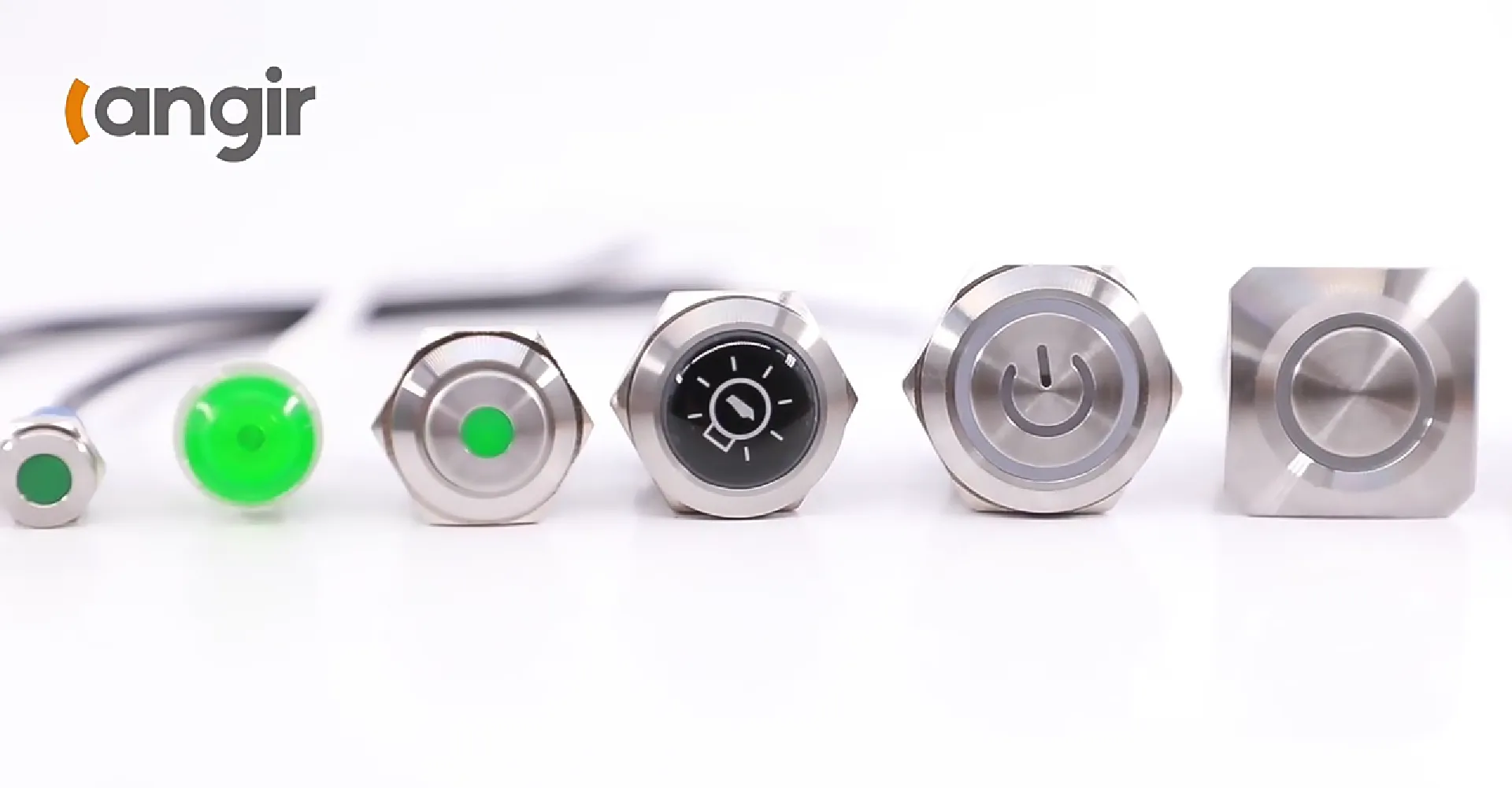
What Are Industrial Push Button Switches and Their Types
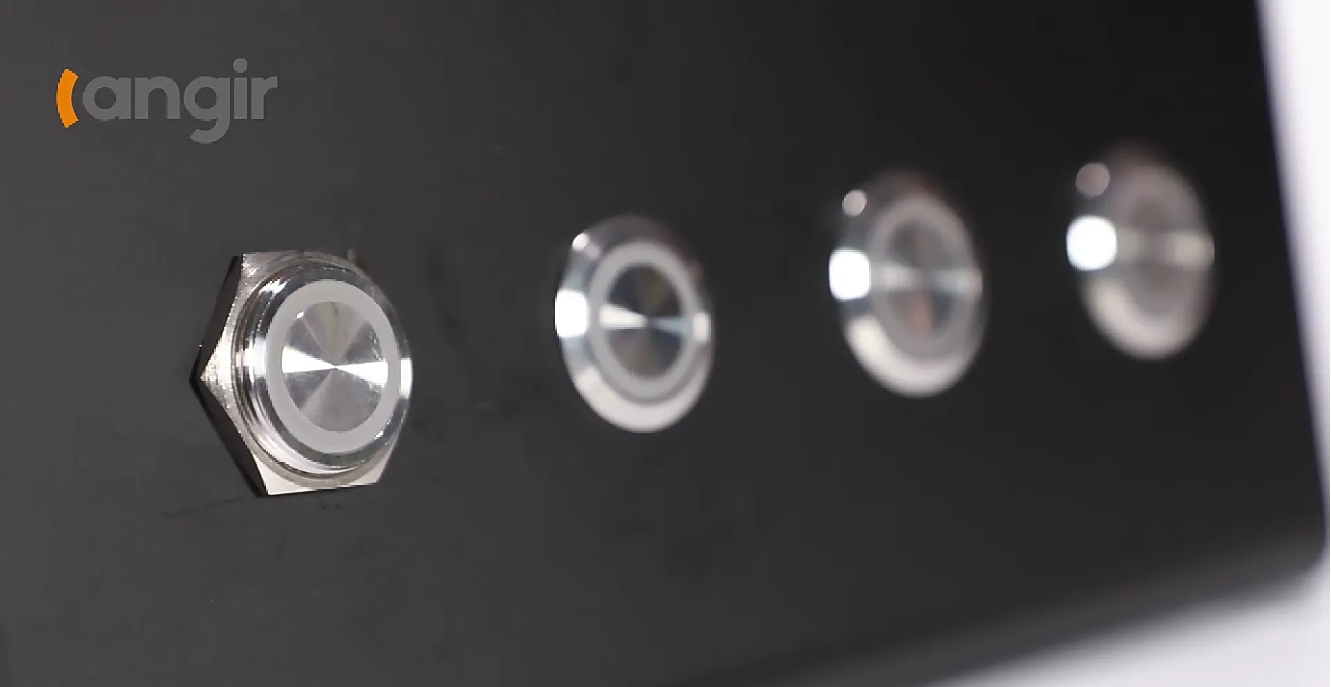
Industrial push button switches are manual control devices that initiate or interrupt electrical circuits on a control panel. They improve operator safety by providing clear actuation feedback and enabling precise machine control. For example, a momentary metal push button can start a conveyor motor then automatically reset when released, reducing accidental run-on.
Contact Langir for Custom Industrial Push Button Switches
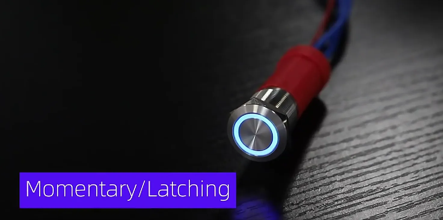
What Are Momentary and Latching Push Button Switches
Momentary switches complete a circuit only while pressed, providing temporary control action. Latching switches, in contrast, maintain their state until pressed again, making them ideal for toggling operations without continuous force.
Key distinctions include:
- Momentary → Immediate circuit closure → Suitable for start/stop commands requiring operator presence.
- Latching → State retention → Ideal for pump on/off controls where continuous operation is needed without holding the button.
Building on actuation type, understanding contact configurations guides proper wiring of normally open and normally closed circuits.
How Do Normally Open (NO) and Normally Closed (NC) Contacts Work
“Normally Open” (NO) contacts remain open with no power, closing only when the button is pressed. “Normally Closed” (NC) contacts are closed at rest and open on actuation.
NO contacts prevent unintended activation, while NC contacts ensure fail-safe shutdowns. These contact principles lead directly into material choices like illuminated or plastic push buttons.
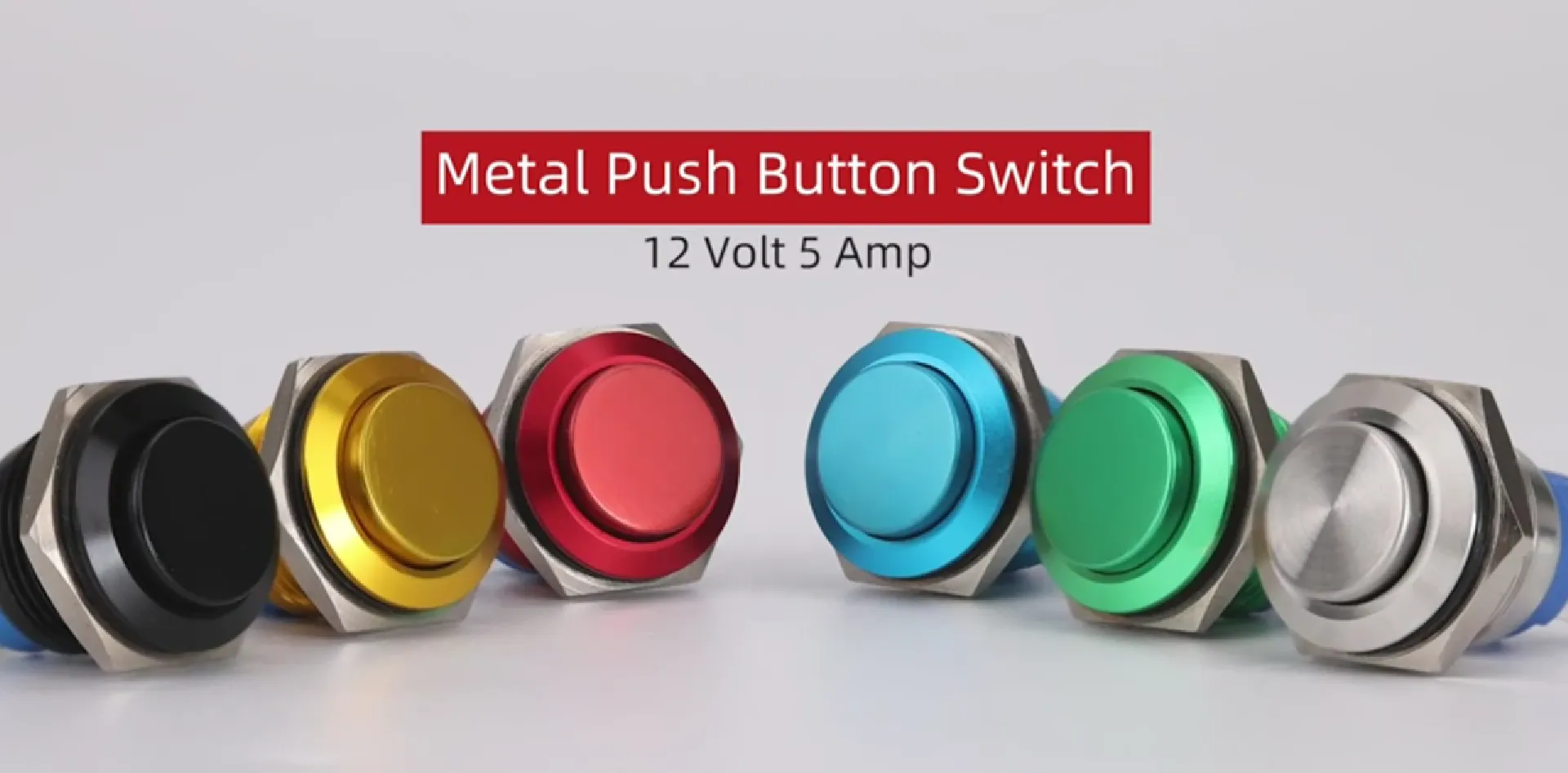
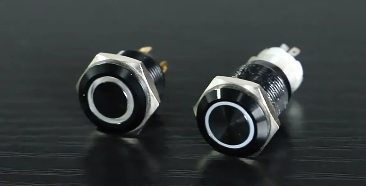
What Are the Differences Between Illuminated, Metal, and Plastic Push Buttons
Before wiring, you must select the appropriate switch body material and illumination feature.
Metal housings excel under harsh environments, while plastic variants offer chemical resistance and lighter weight. Selecting the right configuration prepares you for common panel configurations.
Which Push Button Switch Configurations Are Common in Control Panels
Control panels often deploy SPST, SPDT, DPST, and DPDT switches to manage diverse circuits.
- SPST: Single pole, single throw for simple on/off.
- SPDT: Single pole, double throw to toggle between two circuits.
- DPST: Double pole, single throw to simultaneously control two feeds.
- DPDT: Double pole, double throw for reversible motor control.
Understanding these configurations ensures compatibility with PLC inputs, safety relays, and indicator lights.
What Tools and Materials Are Needed for Push Button Switch Installation
Proper installation requires the right tools, wiring supplies, and safety gear to protect personnel and equipment. Ensuring you have everything on hand avoids delays and rework during panel assembly.
Contact Langir for Custom Industrial Push Button Switches
Which Tools Are Essential for Control Panel Push Button Installation
You need a combination of cutting, fastening, and measurement tools to guarantee precise mounting and reliable electrical connections.
- Electric Drill with Hole Saw Kit for accurate panel cut-outs.
- Wire Strippers and Cable Cutters sized for 16–22 AWG conductors.
- Insulated Screwdrivers (Phillips and flathead) rated for 1000 V.
- Multimeter to verify voltage, continuity, and insulation resistance.
- Torque Wrench for consistent screw terminal tightening.
Having these tools prepped accelerates the mounting process without compromising safety.
What Wiring Materials and Accessories Are Required
Selecting proper wiring components ensures signal integrity and longevity of connections.
- Wire Gauge: 16 AWG for control circuits, 18–22 AWG for indicator LEDs.
- Insulated Terminal Connectors: Ferrules or quick-disconnects rated to switch amperage.
- Heat Shrink Tubing for strain relief and additional insulation.
- Cable Labels for terminal identification and future maintenance.
Using the correct materials minimizes contact resistance and simplifies subsequent troubleshooting.
What Safety Equipment Should Be Used During Installation
Electrical safety starts with personal protective equipment and panel protocols.
- Safety Glasses and Face Shield to guard against metal shavings and sparks.
- Insulated Gloves certified to ASTM D120 for live-parts handling.
- Lockout/Tagout Kit to ensure de-energized panels remain off during work.
- Arc-Flash Clothing rated per NFPA 70E for high-voltage environments.
Wearing proper gear reduces risk and builds confidence in executing precise mounting and wiring tasks.
How to Mount Push Button Switches on Control Panels
Mounting flush and secure push button switches depends on careful panel preparation and alignment techniques.
What Are the Best Practices for Choosing Mounting Locations
Ideal switch placement balances accessibility, ergonomics, and electrical separation.
- Operator Reach Zone: Position frequently used buttons within easy arm’s length.
- Environmental Considerations: Avoid areas prone to moisture or dust ingress.
- Interference Avoidance: Maintain at least 1 inch clearance from high-voltage lines and rotating parts.
Proper location planning prevents accidental activation and eases routine operation, leading into precise panel preparation steps.
How to Prepare the Control Panel for Mounting
Panel readiness involves marking, drilling, and edge finishing for a clean installation.
- Draw precise hole outlines using vendor-supplied templates.
- Drill with the recommended hole saw diameter (16 mm, 19 mm, or 22 mm).
- Deburr edges with a file or deburring tool to prevent seal damage.
Thorough preparation sets the stage for secure fastening and correct switch alignment.
What Are the Steps to Securely Mount Push Button Switches
- Insert the switch body through the panel cut-out until the flange seats flush.
- Thread the locking nut onto the switch’s threaded barrel and hand-tighten.
- Use a torque wrench to apply the manufacturer’s specified torque (typically 2–3 Nm).
- Verify alignment so legends and symbols are upright and legible.
This mounting procedure ensures stable mechanical fit, enabling predictable actuation force and longevity.
What Are the Differences Between Flush, Surface, and Recessed Mounting
Switches can be mounted flush, surface, or recessed based on enclosure style and operator needs.
- Flush Mounting sits the button flange level with the panel face for low-profile design.
- Surface Mounting uses an external bracket to project the switch beyond the panel front.
- Recessed Mounting places the switch below the panel surface to guard against accidental presses.
Choosing the correct style integrates with panel ergonomics and protective requirements, naturally leading to wiring considerations.
How to Wire Push Button Switches in Control Panels
Wiring push buttons requires accurate terminal identification and clear schematics to prevent miswiring.
Contact Langir for Custom Industrial Push Button Switches
How to Identify Push Button Switch Terminals: COM, NO, NC, and LED Pins
Most illuminated push button switches feature four or five pins: one common (COM), one normally open (NO), one normally closed (NC), and two LED pins (+/−). The COM terminal serves as the input feed, and NO/NC pins route the load or safety circuit. LED pins connect to a low-voltage supply (typically 12–24 V DC).
What Are the Wiring Steps for 2-Pin, 4-Pin, and 5-Pin Push Button Switches
Follow these step-by-step instructions to wire different configurations:
- 2-Pin (NO Only): Connect feed to COM, load wire to NO, tighten terminals.
- 4-Pin (NO + LED): COM → feed; NO → load; LED+ → +24 V supply; LED− → common return.
- 5-Pin (NO + NC + LED): COM → feed; NO → load; NC → safety circuit; LED+ → + supply; LED− → ground.
Each wiring type builds on the terminal functions, so interpreting wiring diagrams becomes straightforward.
How to Wire Illuminated Push Button Switches
Illuminated switches combine mechanical contacts with an LED module. Connect the LED+ pin to the control panel’s indicator voltage and the LED− pin to the return. Then wire the COM, NO, and NC terminals as with a standard switch. Always verify LED polarity before energizing to avoid damage.
What Are Common Wire Color Codes and Their Function
Below is a standard wiring color code table for industrial control panels:
Matching colors with terminal assignments streamlines installation and future maintenance.
How to Interpret Push Button Switch Wiring Diagrams
A wiring diagram uses lines to show electrical connections between components. Identify terminals by labels (COM, NO, NC, +, −), match them to your switch pinout, and trace each conductor path through relays or PLC inputs. Clear diagrams reduce troubleshooting time and enhance safety compliance.
How to Test and Verify Push Button Switch Installation
After wiring and mounting, functional testing confirms both electrical integrity and operator control.
Contact Langir for Custom Industrial Push Button Switches
What Are the Steps to Test Push Button Switch Operation
- Restore control panel power following lockout/tagout procedures.
- Use a multimeter to verify COM to NO continuity when pressed and COM to NC when released.
- Observe LED illumination under actuation for proper indicator function.
- Cycle the button repeatedly to confirm mechanical resilience and contact consistency.
Functional verification ensures circuits respond as intended before returning machinery to service.
How to Troubleshoot Common Wiring and Switch Malfunctions
If a button fails to actuate or LED does not light:
- Check terminal tightness and wire integrity.
- Verify correct wire color to terminal mapping.
- Measure LED supply voltage under load.
- Inspect switch body for debris or misalignment.
Systematic troubleshooting rooted in wiring diagrams accelerates fault isolation and correction.
What Are Typical LED Indicator Problems and Solutions
Poor LED performance often stems from incorrect voltage, reversed polarity, or loose connections. Confirm your panel’s LED supply matches the switch rating (12 V vs. 24 V), swap LED wires to correct polarity, and retighten connectors. Restoring proper LED function completes the final validation step.
What Industrial Standards and Compliance Are Required for Control Panel Push Button Installation
Compliance with UL, NEMA, and NFPA standards ensures control panel safety, reliability, and market acceptance.
What Is UL 508A and Why Is It Important for Control Panels
UL 508A is the Underwriters Laboratories standard for the construction of industrial control panels. It specifies requirements for component selection, wiring practices, enclosure ratings, and diagnostic documentation. Meeting UL 508A validates panel safety and expedites regulatory approvals.
Industrial Control Panel Standards
UL 508A is a crucial standard for the construction of industrial control panels, specifying requirements for component selection, wiring practices, and enclosure ratings to ensure safety and regulatory compliance. Meeting this standard is essential for validating panel safety and facilitating regulatory approvals.
This citation supports the article’s emphasis on the importance of UL 508A compliance in control panel installations.
How Do NEMA Enclosure Ratings Affect Push Button Installation
NEMA ratings classify enclosure protection against environmental factors.
NEMA Enclosure Ratings
NEMA ratings are essential for classifying enclosure protection against environmental factors, such as dust, water, and corrosion. Selecting the correct NEMA rating is critical for preserving the integrity and performance of push button switches under varying environmental conditions.
This citation reinforces the article’s discussion of NEMA ratings and their impact on push button switch installations.
What Are NFPA 70 (NEC) and NFPA 79 Compliance Requirements
NFPA 70 (NEC) defines electrical installation codes, while NFPA 79 covers industrial machinery electrical standards. Both mandate conductor sizing, grounding, emergency stops, and labeling. Adhering to these codes reduces fire risk and ensures operator safety.
How to Ensure Your Control Panel Meets Safety and Quality Standards
- Use UL-listed components and follow manufacturer wiring diagrams.
- Label all circuits and switches per NEC Article 110.22.
- Perform dielectric withstand and grounding continuity tests.
- Maintain comprehensive panel documentation and schematic drawings.
These best practices keep your installation audit-ready and performance-reliable.
How Can Langir’s Push Button Switches and Customization Services Support Your Control Panel Needs
Langir manufactures a wide range of industrial push button switches in bulk and offers tailored control panel solutions. With in-house UL certification and NEMA-compliant designs, Langir bridges technical expertise with scalable supply chains.
Contact Langir for Custom Industrial Push Button Switches
What Push Button Switch Types Does Langir Offer in Bulk
Bulk pricing and consistent quality make Langir the go-to partner for large-scale panel projects.
How Does Langir Provide Custom Control Panel Solutions
Langir’s engineering team collaborates on enclosure design, component layout, and wiring harness fabrication. By integrating CAD validation and UL documentation, Langir delivers turnkey panels that meet client specifications and regulatory demands.
Why Choose Langir for Industrial Push Button Switch Supply
- Certified UL 508A production facilities ensure compliance.
- Dedicated R&D team supports rapid prototyping and custom actuator options.
- Global logistics network guarantees on-time bulk deliveries.
- 24/7 technical support offers installation guidance and troubleshooting.
These advantages position Langir as a trusted authority in industrial switch solutions.
How to Contact Langir for Bulk Orders and Custom Inquiries?
For pricing, sample requests, or project consultations, reach out to Langir’s sales team: click here.
Installing and wiring push buttons correctly results in safer, more reliable control panels. By following UL 508A and NEMA best practices, using the right tools, and leveraging Langir’s bulk and custom services, you accelerate deployment and reduce risks. Get started on your next panel project with confidence—partner with Langir for quality switches and expert support.
FAQs
Contact Langir for Custom Industrial Push Button Switches
What are the common mistakes to avoid when installing push button switches?
Common mistakes during push button switch installation include improper wiring, neglecting to secure connections, and failing to follow safety protocols. It’s crucial to double-check terminal connections and ensure that the correct wire gauge is used. Additionally, overlooking the importance of ergonomic placement can lead to operational inefficiencies. Always refer to the manufacturer’s guidelines and ensure compliance with relevant standards to avoid these pitfalls and ensure a successful installation.
How can I ensure the longevity of push button switches in harsh environments?
To enhance the longevity of push button switches in harsh environments, select switches with appropriate NEMA ratings that match the environmental conditions. For instance, use IP65-rated switches for dust and water exposure. Regular maintenance, such as cleaning and inspecting for wear, is also essential. Additionally, consider using protective covers or enclosures to shield switches from extreme temperatures, moisture, and corrosive substances, thereby prolonging their operational life.
What should I do if a push button switch fails to operate after installation?
If a push button switch fails to operate post-installation, first check the power supply to ensure it is functioning correctly. Next, inspect the wiring for any loose connections or damage. Use a multimeter to test continuity between terminals. If the switch is illuminated, verify that the LED is receiving the correct voltage. If issues persist, consult the manufacturer’s troubleshooting guide or consider replacing the switch if it is defective.
Are there specific regulations for emergency stop push button switches?
Yes, emergency stop push button switches must comply with specific regulations, such as those outlined in NFPA 79 and ISO 13850. These standards dictate that emergency stops must be easily accessible, clearly labeled, and designed to immediately halt machinery operation. Additionally, they should be tested regularly to ensure functionality. Compliance with these regulations is crucial for ensuring operator safety and minimizing risks in industrial environments.
How can I customize push button switches for specific applications?
Customizing push button switches involves selecting specific features such as size, color, illumination, and contact configuration to meet application needs. Manufacturers like Langir offer customization options, allowing you to choose materials, switch types, and even branding elements. Collaborating with the manufacturer’s engineering team can help ensure that the switches are tailored to your operational requirements, enhancing both functionality and aesthetics in your control panel design.
What are the benefits of using illuminated push button switches?
Illuminated push button switches provide several benefits, including enhanced visibility in low-light conditions, which improves operator safety and reduces the risk of errors. The LED indicators can also convey the operational status of machinery, providing immediate feedback to users. Additionally, illuminated switches can be customized in color to signify different functions, making them an effective tool for improving user interface and operational efficiency in control panels.
How do I maintain push button switches for optimal performance?
To maintain push button switches for optimal performance, regularly inspect them for signs of wear, dirt, or corrosion. Clean the surfaces with appropriate solvents to prevent buildup that could hinder operation. Ensure that all connections are tight and free from oxidation. Additionally, perform functional tests periodically to verify that the switches respond correctly. Following the manufacturer’s maintenance guidelines will help ensure longevity and reliability in your control panel operations.
Conclusion
Proper installation and wiring of push button switches are essential for creating safe and efficient control panels that comply with industry standards. By utilizing the right tools, materials, and following best practices, you can enhance operational reliability and minimize downtime. Explore Langir’s extensive range of high-quality push button switches and customization services to meet your specific project needs. Start your journey towards safer and more efficient control panel solutions with Langir today.