EN
EN
Struggling with inconsistent LED illumination or unreliable switch activation in your industrial systems? Precision wiring of a 16mm LED push button switch is paramount for seamless control and clear status feedback in demanding environments. This comprehensive guide will equip you with a deep understanding of 16mm LED push button switch functionality, essential tools, critical safety protocols, and detailed step-by-step wiring instructions for 2-, 4-, and 5-pin configurations. We’ll also cover advanced voltage considerations, precise resistor calculations, effective troubleshooting techniques for common issues, and highlight why Langir’s robust L16 series switches are the preferred bulk solution for leading manufacturers. Let’s delve into switch architecture, illumination variations, optimal wiring practices, fault diagnosis, and how to secure a custom quote from Langir.
Understanding the 16mm LED Push Button Switch: Functionality and Core Principles
A 16mm LED push button switch integrates a durable mechanical actuator with integrated illumination, providing both tactile control and visual feedback for critical circuits, particularly in challenging industrial settings. These switches typically feature an LED (available in dot, ring, or bi-color options) and dedicated terminals for common (C), normally open (NO), and normally closed (NC) contacts, alongside specific LED leads. Actuating the button precisely completes or interrupts the NO/NC circuit, while the LED illuminates consistently when correct power and polarity are applied. A thorough understanding of each component is fundamental for achieving reliable operation and unambiguous status indication.

Get a quote for custom LED push button switches from Langir
Key Components and Terminal Identification for 16mm LED Push Button Switches
Before commencing any wiring, a clear understanding of the primary components and their respective functions is essential.
Component Overview:
- Actuator: The robust 16mm metal or plastic button, engineered for precise tactile engagement and switch toggling.
- Housing: A rugged, often waterproof metal body, typically rated IP65–IP68, designed for anti-vandal applications and demanding industrial environments.
- Common Terminal (C): The primary input terminal for the switch contacts, serving as the connection point for the power or signal source.
- Normally Open (NO): The contact that closes upon actuation, establishing a connection to deliver power or a signal to the connected load.
- Normally Closed (NC): The contact that opens upon actuation, interrupting the circuit when the switch is activated.
- LED Anode (+): The positive input terminal specifically for the LED illumination circuit.
- LED Cathode (–): The negative return terminal for the LED, typically connected to ground or the negative power rail.
LED Component Integration and Functionality
LED push button switches seamlessly integrate various LED types—dot, ring, or bi-color—alongside dedicated terminals for common (C), normally open (NO), normally closed (NC) contacts, and specific LED leads. Actuating the switch precisely completes or interrupts the NO/NC circuit, while the LED illuminates reliably when supplied with correct power and polarity, delivering essential visual feedback and enhanced control across diverse industrial applications.
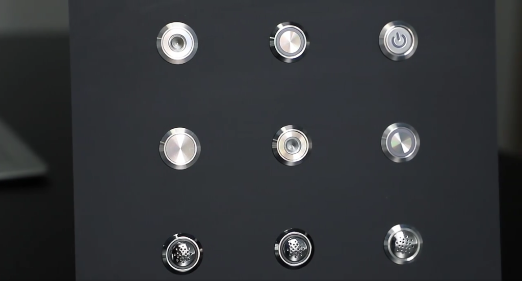
Langir Electric, L16 Series Product Information
This foundational information underpins a comprehensive understanding of the 16mm LED push button switch’s critical components and operational principles.
Collectively, these components constitute a fundamental control element, providing clear status indication through integrated illumination and precise switching. Our next section will delineate the critical differences between momentary and latching actions and their implications for wiring configurations.
Momentary vs. Latching 16mm LED Push Button Switches: Functional Distinctions
The distinction between momentary and latching functions dictates the precise behavior of the switch contacts following actuation.
Momentary switches revert to their default state upon release, making them optimal for transient controls such as start/stop functions. Conversely, latching switches alternate their state with each actuation, proving ideal for persistent on/off toggles. A clear understanding of these operational modes is crucial for correctly integrating the appropriate terminals into your machine’s control circuitry.
Impact of LED Illumination Types on Wiring Configurations
The chosen LED illumination style directly influences both wiring complexity and the nature of visual feedback provided:
- Dot LED: Features a single, centralized light source, requiring only two wires (anode/cathode) for operation.
- Ring LED: Encircles the actuator, utilizing two wires to provide a more diffused and uniform illumination.
- Bi-color LED: Incorporates two anodes sharing a common cathode, or vice versa, necessitating three wires for dual-color status indication.
Wiring for bi-color LEDs typically involves mapping each anode to distinct power sources, such as those for red and green indications. The selection of the appropriate illumination type is critical, as it directly dictates the configuration of your LED supply wiring and the necessary resistor calculations.
This foundational overview of switch anatomy seamlessly transitions into the critical preparation phase, encompassing essential tools, rigorous safety measures, and optimal workspace setup.
Essential Tools and Critical Safety Protocols for 16mm LED Push Button Switch Wiring
Prior to engaging with any electrical circuits, it is imperative to assemble the correct tools and rigorously adhere to fundamental electrical safety protocols to safeguard both personnel and equipment.
Get a quote for custom LED push button switches from Langir
Required Tooling for Optimal Wiring Execution
The following essential tools are required to precisely strip, solder, test, and insulate electrical connections:
- Precision wire strippers for accurate insulation removal.
- A soldering iron (25–40 W) equipped with a fine tip, ensuring robust and secure solder joints.
- A comprehensive heat shrink tubing set, offering assorted diameters for superior insulation and strain relief.
- A high-quality multimeter, indispensable for continuity checks and precise voltage verification.
- Certified safety glasses, providing essential protection against solder splatter and other potential hazards.
Equipping yourself with the appropriate tools is fundamental to achieving clean, reliable wiring that maintains integrity even under conditions of vibration, moisture, or other environmental stressors.
Critical Electrical Safety Measures During Wiring Procedures
Adhere to fundamental precautions when working on control panels:
- Always ensure the main power supply is completely disconnected before initiating any wiring or testing procedures.
- Employ wire gauges that are correctly rated for the intended current (e.g., 22–18 AWG for LED circuits, 16–14 AWG for load circuits).
- Rigorously insulate all exposed conductors using heat shrink tubing or appropriate terminal boots to prevent shorts.
- Confirm correct polarity and verify the complete absence of voltage with a multimeter prior to any soldering operations.
Adhering to these critical safety steps is paramount for preventing short circuits, electrical shocks, and component damage, thereby ensuring a secure and efficient wiring process.
With the necessary tools prepared and stringent safety protocols established, the subsequent section will guide you through precise wiring methodologies for 2-, 4-, and 5-pin switch configurations.
Wiring Methodologies for Diverse 16mm LED Push Button Switch Configurations
Regardless of whether you are working with a straightforward 2-pin indicator or a complex 5-pin control switch, these detailed, step-by-step instructions will ensure the accurate setup of power, load, and LED connections.
Wiring a Basic 2-Pin 16mm LED Push Button Switch
A 2-pin switch is exclusively equipped with LED leads, typically for an “always-on” indicator function. Proceed with the following steps:
- Precisely strip 5mm of insulation from each lead.
- Solder the anode lead to the positive voltage supply (+V, e.g., 24 VDC) via an appropriately calculated resistor.
- Solder the cathode lead securely to ground (0 V).
This configuration results in a continuously illuminated LED, serving as an effective power-on indicator within your control panel.
Wiring a 4-Pin 16mm LED Push Button Switch with Independent LED Control
This configuration utilizes four terminals: two dedicated to the switch contacts (Common/Normally Open) and two for the LED illumination circuit:
- Connect the positive terminal of your power source to the Common (C) terminal.
- Route the Normally Open (NO) terminal to the positive input of your intended load.
- Solder the LED anode to the positive voltage supply (+V) through a correctly sized resistor.
- Connect the LED cathode securely to ground.
This setup ensures that actuating the button activates your load, while the LED illumination remains independently controllable, allowing the indicator to be continuously on or off as required.
Wiring a 5-Pin 16mm LED Push Button Switch with NO/NC Terminals
A 5-pin switch incorporates an additional Normally Closed (NC) terminal, enabling alternate control functionalities:
- Connect the Common (C) terminal to the positive rail of your control power supply.
- Route the Normally Open (NO) terminal to the device’s positive input for activation upon switch depression.
- Route the Normally Closed (NC) terminal to an alternate circuit as required (e.g., an alarm system that deactivates upon switch actuation).
- Solder the LED anode to the positive voltage supply (+V) via a resistor, and connect the cathode to ground.
This comprehensive wiring scheme facilitates dual-circuit control alongside integrated LED feedback, making it ideal for sophisticated panel functions and complex control systems.
Integrating LED Illumination: Constant On vs. Load-Dependent Activation
An “always-on” LED remains continuously illuminated irrespective of the switch’s contact state, whereas an “on-with-load” LED activates only when the switch engages the primary circuit. Select your wiring configuration based on the desired feedback mechanism:
- Constant Illumination: The LED circuit is connected directly to the power supply rails, independent of the Common (C) and Normally Open (NO) contacts.
- Load-Dependent Illumination: The LED anode is connected to the Normally Open (NO) terminal, with the cathode tied to ground, ensuring illumination synchronizes with switch activation.
The choice between these methods should be predicated on whether continuous status indication or activity-based feedback is required for your application.
Calculating the Optimal Resistor Value for LED Illumination
To ensure the longevity and optimal performance of the LED, the correct resistor value must be precisely calculated using Ohm’s Law: .
Precision Resistor Calculation for LED Illumination
For optimal LED protection and performance, calculating the precise resistor value using Ohm’s Law (R = (Vs – Vf) / I) is paramount. This critical step ensures consistent brightness and maximizes LED longevity, laying the groundwork for accurate voltage-specific wiring. The preceding table illustrates practical examples for 12 V, 24 V, and 220 V applications.
Electronics Tutorials, Resistor Calculator
This reference reinforces the article’s guidance on accurately calculating the resistor value for LED illumination, a fundamental aspect of robust wiring.
The meticulous selection of the correct resistor is vital for guaranteeing consistent LED brightness and extended operational life, serving as a crucial precursor to the voltage-specific wiring considerations detailed in the subsequent section.
Advanced Wiring Considerations and Best Practices for 16mm LED Push Button Switches
Within demanding industrial environments, unwavering durability, stringent safety, and regulatory compliance are paramount. The following best practices are designed to assist in engineering exceptionally robust and reliable control panels.

Get a quote for custom LED push button switches from Langir
Voltage-Specific Wiring for 16mm LED Switches (12V, 24V, 220V)
The operational voltage critically influences resistor selection, terminal insulation requirements, and necessary creepage distances:
- 12 V/24 V DC: Employ 1W resistors specifically rated for low-voltage DC applications.
- 220 V AC/DC: Utilize high-voltage rated resistors or dedicated LED drivers, ensuring reinforced insulation and adequate clearances.
- Always adhere to specified IP rating requirements and maintain appropriate clearances, particularly in AC installations, for optimal safety and performance.
It is imperative to adjust wiring paths and insulation standards meticulously to align with the specific voltage class of your control panel.
Wiring Considerations for Anti-Vandal 16mm Push Button Switches
Anti-vandal switch models, typically featuring robust stainless steel bodies, introduce additional layers of protection that influence wiring practices:
- Utilize sealed solder-lug or pre-wired lead variants to rigorously maintain their specified IP67 or higher environmental protection rating.
- Implement robust strain reliefs and cable glands on the panel’s reverse side to effectively prevent water ingress and ensure cable integrity.
- Ensure proper grounding of the metal housing if mandated by local electrical codes, enhancing overall system safety.
Adhering to these steps is crucial for preserving the switch’s inherent ruggedness and ensuring unwavering long-term reliability in challenging operational environments.
Best Practices for Secure and Durable Wiring Connections
Achieving reliable terminations is paramount for connections that must withstand rigorous industrial conditions, including shock, vibration, and extreme temperature cycles:
- Reinforce all solder joints with heat-shrink tubing to provide superior insulation and prevent corrosion.
- Employ high-quality terminal blocks or spade connectors that are precisely rated for the anticipated current load.
- Neatly bundle and route all wiring using cable ties and protective ducts to prevent chafing and maintain an organized panel.
Implementing secure and meticulously executed wiring significantly extends the operational service life and substantially reduces maintenance downtime in critical industrial control systems.
With robust and meticulously executed wiring established, you are now prepared to systematically diagnose and resolve issues should unexpected operational anomalies arise.
Troubleshooting Common Wiring Issues in 16mm LED Push Button Switches
When confronted with non-illuminating LEDs or unresponsive loads, a systematic approach to fault diagnosis is critical for minimizing costly downtime.
Diagnosing Non-Illuminating LEDs
Common causes for a dark LED include:
- Incorrect polarity between the anode and cathode terminals.
- Absence of a current-limiting resistor, or an undersized resistor impeding proper current flow.
- Insufficient supply voltage, falling below the LED’s specified forward voltage.
- A compromised connection, such as a loose solder joint or a fractured wire lead.
Systematically verifying each of these potential factors will facilitate rapid restoration of LED illumination.
Troubleshooting Load Activation Failures
If actuating the button fails to switch your device, consider the following:
- Misidentification or incorrect swapping of Normally Open (NO) and Normally Closed (NC) terminals.
- The Common (C) terminal is not correctly connected to the designated power source.
- Degraded or damaged switch contacts, particularly in high-usage anti-vandal models.
- Issues within the external wiring, or a blown fuse in the upstream circuit.
Performing a continuity check across the Common (C) and Normally Open (NO) terminals while actuating the switch is an effective method to isolate internal contact faults from external circuit anomalies.
Why Langir’s 16mm LED Push Button Switches Are the Optimal Choice for Industrial Applications
Langir Electric engineers exceptionally rugged 16mm LED switches, earning the unwavering trust of OEMs and industrial clients globally. Our L16 series seamlessly integrates unparalleled durability, rigorous certifications, and extensive customization capabilities.
Key Features and Certifications of Langir’s L16 Series LED Switches
Langir’s L16 series switches offer:
- Robust IP65–IP68 and IK10 rated housing, engineered for unwavering performance in the most extreme industrial environments.
- Comprehensive CE, RoHS, REACH, and ISO 9001 certifications, ensuring superior quality, environmental compliance, and global market acceptance.
- Premium construction from stainless steel or nickel-plated brass materials, providing exceptional corrosion resistance and extended operational life.
These rigorous credentials collectively guarantee safe, reliable, and long-lasting performance across virtually any demanding industrial application.
Langir’s Commitment to Customization and OEM/ODM Services
Beyond our extensive catalog of standard products, Langir excels in delivering precisely tailored solutions to meet unique project requirements:
- Precision custom laser etching for symbols, legends, and branding.
- Factory pre-assembled wire harnesses, complete with specified connectors or soldered leads, for streamlined integration.
- Specialty illumination options, including bi-color LEDs, precisely configured to align with your specific control scheme and visual indicators.
Our OEM partners gain a distinct competitive advantage through flexible low Minimum Order Quantities (MOQs), accelerated prototyping cycles, and dedicated technical support from Langir’s expert in-house R&D team.
Requesting a Quote or Placing a Bulk Order for Langir 16mm LED Push Button Switches
Prepared to optimize your production processes with exceptionally reliable, illuminated switches? Connect with Langir today for bulk orders and bespoke customization services. Receive a prompt, comprehensive quote for our L16 series 16mm LED push button switches, meticulously tailored to integrate seamlessly into your industrial designs.
Langir’s unparalleled expertise in engineering anti-vandal and high-performance industrial switches firmly establishes us as the preferred partner for manufacturers requiring robust, rigorously certified control components.
By mastering the intricacies of 16mm LED switch wiring—from a profound understanding of components and strict adherence to safety protocols, to precise resistor selection and the application of advanced best practices—you guarantee crisp, consistent illumination and unwavering load control across every panel. Partner with Langir to procure high-quality, customizable switches engineered to withstand the most demanding environments, thereby streamlining your bulk procurement process and enhancing overall system reliability.