 EN
EN
This handy guide focuses on how to wire an illuminated push button switch, specifically the 4-pin variety. For those who may not be familiar, an illuminated push button switch is a simple yet effective component typically used to add a visual element to your gadgets and projects. To get started, you’ll need a few tools: wire strippers, a soldering iron (if you’re feeling adventurous), and some stranded wire. Make sure to grab your switch and review its pin layout, which usually consists of two pins for power and two for the illumination feature.
These are generally labeled on the switch itself or in the accompanying documentation. One pin connects to the positive terminal of your power source, while the other pin connects to the device you’re controlling. The illumination feature usually requires a separate connection to your power source, specifically to ensure the light turns on when the button is activated. For this, connect one of the illumination pins to the positive side of your power, and the other to ground. Once everything is snugly wired, give yourself a moment to admire your handiwork and then test the switch. With any luck, the button will light up like a tiny beacon of hope, making all your hard work worth it.
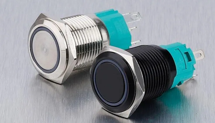
Illuminated Push Button Switch and Its 4 Pins
This section explains the basics of an illuminated push button switch with a 4-pin configuration. It is widely available through illuminated push button switch wholesale channels that cater to diverse applications. In simple terms, the switch has four distinct terminals that serve different functions. One terminal connects to the power, one to the load, another acts as ground, and the last one drives the LED illumination. This means every pin has a role in making sure your switch not only controls a circuit but also lights up to signal its status. For additional support, feel free to contact Langir.

Contact Langir for Custom Illuminated Push Button Switches
The Power, Ground, Load, and LED Terminals on a 4 Pin Switch
The power terminal brings the supply voltage into the switch, while the ground terminal completes the circuit. The load terminal directs the current to the device being controlled, and the LED terminal is dedicated to lighting the button. Each connection creates a specific pathway, ensuring that the circuit operates safely and efficiently. This clear pinout makes troubleshooting straightforward, even for beginners.
Normally Open and Normally Closed Functions in Your Switch
Push button switches can work as normally open (NO) or normally closed (NC). In a normally open configuration, the circuit remains incomplete until the button is pressed, allowing current to flow only momentarily. Conversely, with a normally closed setup, the circuit is completed by default and the press creates a temporary break in the flow of electricity. Understanding these differences is vital for incorporating the right switch type into your project.
Common Types of Illuminated Push Button Switches Available
There are several common types available in the market. For example: 1. Panel Mount Push Buttons – Often used in control panels where durability and ease of access are needed. 2. Surface Mount Push Buttons – Ideal for compact devices and circuit boards where space is limited. 3. Waterproof Push Buttons – Designed for outdoor or industrial applications with protection against water and dust. Each variant is designed to provide reliable performance while ensuring that the LED remains bright even under different electrical conditions.
How the Internal LED Circuit Operates Within a 4 Pin Design
Inside these switches, a small LED circuit works to indicate whether the switch is activated. When power flows through the appropriate LED pin, a resistor limits the current to a safe level, protecting the LED from burning out. This simple yet effective design ensures a prolonged lifespan and helps prevent common issues such as flickering.
Key Electrical Ratings to Verify for Your 4 Pin Switch Wiring Project
Before wiring your switch, check electrical ratings like voltage, current capacity, and power dissipation. Matching your switch with the right ratings is crucial to avoid issues like voltage drop or short circuits. Using the correct wiring gauge and ensuring proper insulation are also essential steps to guarantee safe operation.
Essential Tools and Safety Measures
Working with electrical components means you need the right tools and a safe workspace. Gather quality screwdrivers, a soldering iron, wire strippers, and a multimeter. These tools are essential for measuring and confirming the integrity of each connection.

Contact Langir for Custom Illuminated Push Button Switches
Gathering the Necessary Wiring Implements and Connectors
Reliable wires, terminal connectors, and heat shrink tubing are necessary for a neat jobs. Using the right type of connectors ensures stable and lasting connections, eliminating the risk of loose terminals that might lead to shorts or malfunctions.
Selecting Suitable Wires for Your Illuminated Push Button Switch Setup
Make sure to choose wires that can carry the expected current without overheating. Wires with proper insulation and gauge prevent issues like voltage drop and interference, ensuring the entire circuit remains stable and efficient.
Observing Fundamental Electrical Safety Guidelines During Installation
Always disconnect power before starting any wiring work. Wear safety glasses, avoid touching live circuits, and make sure your work area is dry and non-conductive. These precautions help prevent accidents like shocks or fires while ensuring safe and professional results.
Preparing Your Work Area for a Secure Wiring Procedure
A clean, organized workspace reduces mishaps during installation. Set up an anti-static mat, clearly mark wire lengths, and secure all tools nearby so there are no sudden interruptions during the wiring process.
Understanding Voltage and Amperage for Your Illuminated Switch
Knowing the voltage and current requirements for both the LED and the switch is critical. This prevents miswiring that could result in component failure. A multimeter can verify that each connection meets the expected levels, giving you confidence in your installation.
Decoding the 4 Pin Push Button Switch Wiring Diagram
Understanding wiring diagrams can feel like learning a new language—but it’s all about reading the symbols. The diagram for a 4-pin switch shows each pin’s function and interconnection with the overall circuit.
Contact Langir for Custom Illuminated Push Button Switches
Interpreting Standard Symbols in a 4 Pin Push Button Switch Wiring Diagram
In diagrams, symbols represent power sources, grounds, loads, and LEDs. Each symbol is standardized so that you can easily match them with actual terminals on your switch. The power symbol, for instance, typically looks like a plus sign, while ground is represented by multiple descending lines.
Matching Diagram Terminals to Your Actual Illuminated Push Button Switch
Once you understand the symbols, compare them with the physical switch. Ensure each terminal on the switch corresponds correctly to the diagram. This visual matching minimizes errors and ensures the wiring will operate as intended.
Recognizing Various Illumination Wiring Approaches in Schematics
Different diagrams might show alternate methods for integrating the LED. Some use resistors within the circuit explicitly, while others integrate them internally. Knowing these differences lets you adapt the wiring to suit your available components and desired lighting effect.
Finding Accurate Wiring Diagrams for Your Specific Switch Type
Always refer to the manufacturer’s schematic provided with your switch. These diagrams offer the most reliable guidance and keep your project in line with industry standards. Cross-reference any online diagrams with the product manual for extra security.
Typical Errors to Sidestep When Reading a 4 Pin Switch Wiring Diagram
Common mistakes include misidentifying the load terminal or skipping the insulation requirements for high-voltage connections. Double-check each connection with a multimeter and verify that every symbol aligns with an actual pin on your switch.
Step-by-Step Guide to Wire Your Illuminated Push Button Switch
Here’s a clear guide to help you wire your switch confidently. Follow these steps closely for a reliable setup.

Contact Langir for Custom Illuminated Push Button Switches
Preparing Wire Ends for Connection to the 4 Pin Switch
Strip the wires to the correct length—enough to fit securely into the terminals without leaving excess exposed copper. A proper cut ensures tight connections and minimizes the risk of short circuits.
Connecting the Input Power Source to the Illuminated Push Button Switch
Attach the power wire to the designated terminal. Ensure that the connection is firm, using either screw terminals or soldered joints. This connection brings the required voltage into the circuit and is vital for overall operation.
Wiring the Device or Circuit to Your 4 Pin Push Button Switch Output
Connect the output wire from the load side of your switch to the device you plan to control. This wiring completes the circuit when the button is pressed. Make sure every connection is secure and that there is proper insulation around each terminal.
Completing the Connections for the Switch’s LED Illumination
Wire the LED terminal in line with the circuit so that when the switch is activated, the LED lights up. Use a resistor inline if it’s not incorporated internally to limit current and protect the LED.
Ensuring All 4 Pin Switch Wiring Connections Are Secure and Insulated
Once wired, check every connection with a multimeter. Wrap or insulate each terminal with electrical tape or heat shrink tubing to prevent accidental shorts. This extra step ensures long-term reliability and safety.
Common Wiring Configurations for an Illuminated Push Button Switch
Different wiring setups can change how your switch and LED behave. Below are some typical configurations you might use for various applications.

Contact Langir for Custom Illuminated Push Button Switches
Wiring the LED to Activate When the Switch Is Engaged
In this configuration, the LED lights only when the button is pressed. This setup visually signals when the circuit is closed and the device is activated, making it clear for users.
Establishing Constant LED Illumination Regardless of Switch Position
Sometimes the LED may need to be on constantly to indicate power presence. This wiring approach bypasses the switch in the LED circuit so that the indicator remains lit regardless of the switch state.
Implementing 4 Pin Switch Wiring for a Momentary Operation
Some applications require the switch to work momentarily—activating a device only as long as the button is held. This momentary configuration often utilizes a normally open setup that returns to the off state immediately after release.
Configuring a Latching Function With Your Illuminated Push Button Switch
Latching wiring keeps the circuit closed until an external reset occurs. This is perfect for applications where you want the button to toggle between states without continuous pressure.
Adjusting Wiring for Different LED Voltage Requirements in Your Switch
Ensure you adjust resistors and wiring paths if using an LED that requires a different voltage. This careful adjustment prevents voltage mismatch issues and guarantees optimal illumination and function.
Testing and Troubleshooting Your 4 Pin Switch Wiring Connections
After wiring, it’s crucial to test your work properly. Start by verifying all connections are secure. Use a multimeter to check that the voltage is reaching the correct terminals and that the LED lights as expected when the button is pressed.

Contact Langir for Custom Illuminated Push Button Switches
Performing Initial Safety Verifications Before Applying Power
Before you power up the circuit, double-check all connections for proper insulation and verify that the wiring layout matches the provided diagram. This safety step is essential to prevent accidental shorts or heating.
Methods to Confirm Correct Switch Operation and Illumination
Apply power briefly while observing the LED and device. If the LED lights when the button is pressed and the device operates correctly, the wiring is successful. If not, re-check each terminal connection carefully.
Diagnosing Reasons Your Illuminated Push Button Switch LED Fails to Light
Common causes for LED failure include poor solder joints, misconnected wires, or insufficient resistance. Use a multimeter to trace the voltage drop along the LED circuit and identify any issues.
Resolving Issues When the Switched Circuit Does Not Function
If the circuit remains inactive, re-inspect the load and power connections. Verify that the switch itself is functioning and that no pins are cross-connected. Correcting these issues usually fixes the problem swiftly.
Maintaining the Long-Term Integrity of Your 4 Pin Switch Wiring
For ongoing reliability, periodically inspect connections for any signs of wear or corrosion. Use high-quality connectors and work in a dry, controlled environment to ensure your wiring stands the test of time.
How to Wire a 4-Pin Illuminated Push Button Switch | FAQs
What does each pin on a 4-pin push button switch do?
One pin supplies power, one acts as the load connector, another is ground, and the last drives the LED for illumination.
How can I test my switch wiring before full installation?
Use a multimeter to verify voltage at each terminal and check for continuity, ensuring all connections are secure and properly insulated.
Why might the LED in my illuminated push button switch not light up?
Common reasons include miswiring, a missing resistor, poor solder joints, or an incompatible LED voltage requirement.
Is it safe to wire these switches on my own?
Yes, if you follow proper safety guidelines—disconnect power, use the right tools, and double-check all connections, you can wire the switch safely.
What maintenance should I perform on my wiring setup?
Regularly inspect for corrosion or loose connections, and use high-quality connectors and insulation to ensure long-term reliability.