EN
EN
Welcome to this hands-on guide on wiring a 5 pin push button switch with LED. This article will walk you through the process—from identifying pins to testing your installation. For anyone working in industrial manufacturing, langir’s reliable push button switches, available as push button switch wholesale, offer customization and bulk purchasing at low MOQs. With a friendly, no-nonsense approach, we’ll break down each step so you feel confident in setting up your switch wiring system. Let’s dive in, get your LED lit up, and if you need any further assistance, contact Langir for more personalized support!
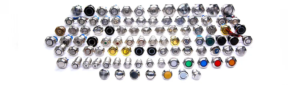
5 Pin Push Button Switch With LED
Contact Langir for Custom Push Button Switches
Identifying Each Pin on Your Metal Power Button
Start by getting familiar with your switch. Each pin on a 5 pin push button switch serves a unique purpose. One pin typically connects to the power source, while another goes to the LED positive connection. The remaining pins handle load, grounding, or signal feedback. When working with metal power buttons, check if the body of the switch is connected to ground. This ensures safe operation and minimizes interference. Mark your pins based on manufacturer diagrams for accuracy, as misidentifying a pin can lead to wiring errors or device failure.
Common Types of 5 Pin Push Button LED Switches
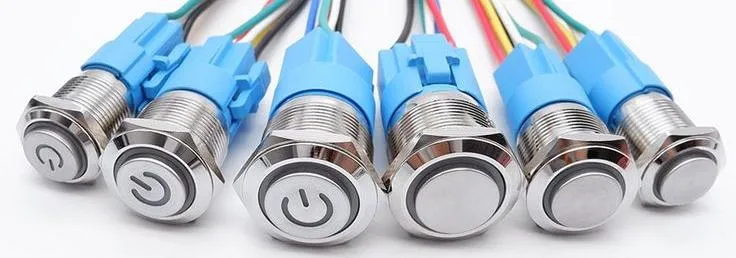
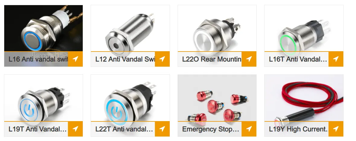
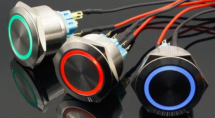
Different models of 5 pin switches exist. Some are designed with a permanently illuminated LED, while others only light when the button is pressed. Also, there are variants built in corrosion-resistant materials like aluminium or brass. You might find switches that support three-way functions for complex automation setups. No matter the model, verify that the switch meets national electrical code standards and is tested for durability. Consider factors like the volt rating, insulation quality, and ease of connection with screw terminals for a secure fit.
Essential Tools and Materials for Switch and Wiring
Before starting, assemble essential tools: a screwdriver, wire stripper, multimeter, soldering iron, and appropriate cables. Materials should include the switch, wires of the proper gauge, connectors, and, if needed, extra resistors to protect your LED from excess voltage. Using quality materials will help prevent problems such as corrosion or overheating. It’s always worth investing in a solid junction box and insulating tape to keep everything neat and safe.
Safety Precautions Before Starting Your Wiring Project
Safety first! Always disconnect your power source before handling any wiring. Use an insulated work surface and wear safety glasses. Double-check that the voltage levels are appropriate for the switch and LED to avoid damaging components. Follow local electrical codes, and if you’re ever in doubt, consult a professional electrician. Taking these precautions guarantees not just a successful installation but also your personal safety.
Reading a Basic 5 Pin Push Button Switch Wiring Diagram
A wiring diagram is your roadmap to success. Begin by comparing your physical switch to the diagram provided by the manufacturer. Note where the power, load, LED positive, LED negative, and ground pins are placed. A clear diagram helps avoid miswiring errors, ensuring that the LED lights up correctly. Use a multimeter to check continuity as you connect each pin, verifying that every connection aligns with the schematic.
Preparing for the 5 Pin Switch Wiring Process
Contact Langir for Custom Push Button Switches
Selecting the Correct Wire Gauge for Your Application
Choose wires that can handle the current of your circuit. Generally, a 22 to 18 gauge wire works well for most LED and low-current applications. Thicker wires may be required if your load demands more power. Proper wire gauge selection affects both safety and performance.
Stripping and Preparing Wires for Connection
Strip the insulation carefully, leaving enough exposed wire for a good connection but not so much that wires might short. Trim wires to a neat length and twist strands together if using stranded wire. This minimizes the risk of accidental shorts and creates a clean, lasting connection.
Understanding Your Power Source and Load
Before wiring, know your circuit’s power requirements. Confirm that your power source—be it a DC supply or battery—matches the LED’s voltage and current ratings. The load may include additional components, so plan accordingly. Having a clear picture ensures compatibility across the board.
Planning Your 5 Pin Connector Wiring Layout
Draw a simple schematic of your layout. Arrange the wires from the power source, through the switch, to the load and LED. Label each connection clearly. A planned layout ensures you aren’t scrambling mid-project and helps with troubleshooting later.
Testing Your Push Button LED Light Functionality Pre-Installation
Before finalizing everything, test the LED separately with a known good power supply and resistor. Check that it lights up as expected. This step gives you confidence that the LED and switch are fully functional when integrated into the final circuit.
Step-by-Step 5 Pin Push Button Switch Wiring Diagram Implementation

Contact Langir for Custom Push Button Switches
Connecting the Power Source to the Switch
Connect the positive output from your power supply to the pin designated for power. Make sure connections are secure with screw terminals or soldered joints. A clean connection ensures minimal voltage drop and reliable performance over time.
Wiring the Load to the Switch Output
The load, which could be a relay or additional LED setup, connects to the switch’s output pin. Ensure that the load’s positive pin matches with the switch’s output. Follow your wiring diagram closely to avoid any misconnection between load and power.
Integrating the LED Positive Pin Connection
Wire the LED’s positive line to its associated pin on the switch. This connection lets the LED offer immediate feedback when the button is pressed. If your design requires an always-on indicator, consider a parallel circuit with an additional resistor for current regulation.
Grounding the LED Negative Pin Correctly
Proper grounding is crucial. Connect the LED negative pin and any unused ground pins to the common ground. A stable ground prevents stray voltages and ensures the entire circuit operates safely. Confirm that each ground connection is secure, especially in metal switch assemblies.
Verifying Connections Against Your 5 Pin Switch Wiring Diagram
With all wires connected, compare your setup against the manufacturer’s diagram. Use a multimeter to check for continuity and correct voltage levels. Verifying connections reduces the risk of failure once power is restored.
Configuring the Push Button LED Light Illumination
Contact Langir for Custom Push Button Switches
Wiring for Always-on LED Indication
If you want the LED to remain lit as an indicator, wire the positive pin to a constant power source with an appropriate resistor. This method provides a visual cue that the circuit is powered at all times. Adjust resistor values based on the LED’s voltage and current ratings.
Setting Up LED Activation When the Switch Is On
For a setup where the LED only lights when the button is pressed, wire it so that the LED circuit is completed solely during actuation. This configuration conserves power and clearly shows when the switch is active. It’s ideal for low-power signaling applications.
Options for Independent LED Control
Consider using a microcontroller for independent LED control. This enables programmable patterns or dimming effects when the button is pressed. Independent control provides extra flexibility for advanced automation systems.
Resistor Requirements for LED Protection in 5 Pin Switch Wiring
Always include a resistor in series with your LED to limit current and prevent burnout. Calculate the resistor value using Ohm’s law based on your supply voltage and LED forward voltage. A precise resistor value helps extend the LED’s lifespan significantly.
Troubleshooting Common Push Button LED Light Issues
If your LED isn’t lighting, first check all connections against your wiring diagram. Look for loose connections or misplaced wires. Use the multimeter to rule out power supply problems and verify that the resistor is functioning correctly. Troubleshooting step-by-step saves time and anxiety.
Advanced Considerations for 5 Pin Connector Wiring and Metal Power Buttons
Contact Langir for Custom Push Button Switches
Using a 5 Pin Connector for Easier Installation and Removal
A dedicated 5 pin connector makes installation straightforward. It allows for modular connections and simpler maintenance. Connectors also reduce the risk of accidental disconnections, an essential aspect for demanding industrial environments.
Waterproofing Your Metal Power Button Installation
In industrial settings, weatherproofing is key. Use silicone sealants and waterproof housings around the metal power button to protect against moisture. Proper sealing ensures longevity and reliable performance even in harsh conditions.
Integrating Your 5 Pin Switch With Microcontrollers
For advanced automation, integrate your switch with a microcontroller. This opens opportunities for programmable functions, detailed logging, and remote control. Many projects benefit from such integration, ensuring precision and repeatability in operations.
Paralleling Multiple Push Button LED Lights
When a project requires multiple indicators, paralleling LED circuits can save space and simplify wiring. Ensure that each LED has its own resistor for consistent brightness. Paralleling requires careful planning to avoid overloading the circuit.
Specifics of a 5 Pin Ignition Switch Wiring Diagram if Applicable
Some applications might require ignition switch wiring specifics. In these cases, adhere strictly to the manufacturer’s instructions. This ensures safe and efficient operation, particularly in systems like engines or heavy machinery.
Testing and Finalizing Your 5 Pin Push Button Switch Installation

Contact Langir for Custom Push Button Switches
Performing Initial Power-Up Tests Safely
Before full deployment, conduct a low-voltage power-up test. Check for correct voltage at the LED and switch. Test the push button actuation to see if the LED responds appropriately. This early testing prevents potential damage later.
Checking Switch Actuation and LED Response
After powering up, press the switch multiple times to verify consistent response. Look for any delays or weak illumination that could indicate connection issues. A reliable switch should display immediate LED activation and deactivation.
Securing All Connections and Mounting the Metal Power Button
Once testing is complete, secure your wiring with cable ties or heat-shrink tubing. Mount the metal power button firmly in its enclosure using appropriate screws. A secure installation protects against vibration and accidental disconnections.
Final Inspection of Your Switch and Wiring Setup
Do a final inspection comparing your setup with the wiring diagram. Ensure there’s no stray wiring, and all connections are tight and clean. This last check is essential before the system is fully integrated into your operation.
Documenting Your 5 Pin Push Button Switch Wiring Diagram for Future Reference
Keep a detailed record of your wiring layout, including photographs and diagrams. Documentation aids in future troubleshooting or upgrades, ensuring that any technician can understand and work with your installation.
How to Wire a 5 Pin Push Button Switch With LED | FAQs
What is the purpose of the 5 pins in the push button switch?
The five pins serve distinct roles including connecting power, transmitting the load, and controlling the LED. Each pin is mapped based on the manufacturer’s diagram for proper functionality.
How do I ensure my LED does not burn out?
Include a resistor in series with the LED calculated using Ohm’s law. This limits current and prevents excessive voltage from damaging the LED.
What should I do if the LED does not light up at all?
Double-check all wiring connections and test components with a multimeter. Verify that the power supply is active and that the push button is making full contact when pressed.
Can I integrate this switch with a microcontroller for additional features?
Yes, connecting the switch to a microcontroller allows programmable control, enabling features like dimming or customized LED patterns—ideal for automation projects.
What safety measures should be taken during installation?
Always disconnect power before starting, use insulated tools, and verify voltage levels with a multimeter. Following proper safety precautions helps prevent shocks and equipment damage.