EN
EN
Wiring a panel-mount switch correctly is crucial to avoid downtime, equipment damage, and the hassle of troubleshooting. This comprehensive guide will walk you through component definitions, wiring mechanisms, and practical examples for push button, toggle, and rocker switches. Plus, you’ll get safety best practices, troubleshooting tips, and advice on selecting customized bulk solutions. Whether you’re setting up a simple on/off actuator or a multi-function illuminated switch, our guide covers:
- Key components and terminal functions
- Step-by-step push button wiring (2-, 3-, 4-, and 5-pin)
- Toggle switch diagrams (SPST, SPDT, DPDT)
- Rocker switch configurations (basic, illuminated, multi-position)
- Installation best practices, grounding, and surge protection
- Troubleshooting common wiring issues
- Specifications, IP ratings, and Langir’s OEM/ODM customization services
Discover our complete range of panel switches here: Panel Switches Category
Understanding the Key Components and Terminals of a Panel Mount Switch
Getting started with panel mount switch wiring means knowing the role of each part. A panel mount switch is an electrical switch installed through a control panel, featuring terminals that connect power, load, and optional indicators.
Essential components include:
- Actuator – The button, rocker, or toggle that the operator presses.
- Housing – Panel-mounted enclosure providing mechanical support and environmental sealing.
- Terminals – Metal posts or screws labeled COM, NO, NC, LED+, LED–.
- Sealing Gasket – Ensures IP rating by preventing moisture ingress.
Properly identifying terminals prevents wiring errors and ensures reliable operation.
Get a quote for custom panel-mount switches from Langir
Terminal Types
This breakdown clarifies how each terminal contributes to circuit behavior and indicator functionality.
Decoding COM, NO, and NC Terminals: Their Meaning and Functionality
COM, NO, and NC define a switch’s basic circuit logic. COM (Common) is the input for voltage or ground. NO (Normally Open) completes a circuit only when the switch is pressed, while NC (Normally Closed) breaks a circuit upon actuation. For example, wiring a motor starter through COM → NO ensures the motor only runs when the button is pressed.
Understanding this mechanism guides correct wiring for on-demand control or safety shutdown applications.
Terminal Functions in Electrical Switches
Electrical switches, including panel mount switches, utilize terminals such as COM, NO, and NC to control the flow of electricity. These terminals are essential for the proper functioning of circuits, with COM serving as the common input, NO completing a circuit when activated, and NC breaking a circuit upon activation [1]. Understanding these terminal functions is crucial for correct wiring and ensuring the intended operation of the switch.
Electrical Engineering Handbook (2005)
This research provides fundamental definitions of electrical components, which are essential for understanding the function of terminals in panel mount switches.
Wiring LED and Multi-Function Terminals on Panel Mount Switches
Illuminated and multi-function switches add LED terminals beyond COM/NO/NC. Typically:
- Identify LED+ and LED– on the switch body.
- Connect LED+ to the positive supply (often through a resistor if not internal).
- Tie LED– to ground or negative return.
- Wire COM, NO, and NC as standard.
With this wiring, the LED indicates switch status independently from the main load circuit, supporting visual feedback in control panels.
Essential Tools and Materials for Wiring a Panel Mount Switch
Efficient panel mount switch installation requires consistent, safe tools:
- Wire stripper and cutter for precise insulation removal.
- Crimping tool and insulated connectors for secure terminal joints.
- Multimeter to verify continuity and voltage.
- Heat-shrink tubing and electrical tape for insulation.
- Soldering iron (for solder-type terminals).
Preparing the right supplies minimizes wiring faults and reinforces long-term reliability.
Step-by-Step Guide to Wiring a Push Button Panel Mount Switch
A push button switch offers momentary or latching control. Correct wiring guarantees expected behavior and durability.
Get a quote for custom panel-mount switches from Langir
Wiring a 2-Pin Push Button Switch for Simple On/Off Control
Define: A 2-pin switch has only COM and NO or COM and NC.
Reason: It provides a basic on/off circuit with minimal terminals.
Example: Power → COM, Load → NO for momentary activation.
Steps:
- Strip 6–8 mm of insulation from each conductor.
- Crimp a female spade connector to the power lead.
- Slide connector onto COM terminal.
- Connect load lead to NO terminal.
- Secure switch in panel and test operation.
This configuration suits simple circuit break or signal triggers.
Wiring a 3-Pin Push Button Switch with COM, NO, and NC
A 3-pin switch adds NC for default-closed circuits.
Definition: COM feeds the circuit, NO energizes on press, NC de-energizes on press.
Use case: Safety interlocks default active until button is pressed.
Wiring steps:
- Attach supply positive to COM.
- Connect device power lead to NO for momentary activation.
- Optionally, wire alarm or indicator to NC to run until button press.
Testing with a multimeter confirms switching action between COM–NO and COM–NC terminals.
Connecting 4-Pin and 5-Pin Push Button Switches with LED Indicators
4- or 5-pin switches integrate an LED circuit plus COM/NO/NC contacts.
- 4-Pin: COM, NO, LED+, LED–
- 5-Pin: COM, NO, NC, LED+, LED–
Connection list:
- Wire COM → positive supply.
- Wire NO (or NC) → load.
- Wire LED+ → positive supply (through resistor if needed).
- Wire LED– → ground.
The LED provides constant visual feedback while the contacts control the load independently.
Testing a Wired Push Button Switch for Proper Functionality
After wiring, always verify:
- Use a multimeter to check COM–NO resistance—should be open until pressed.
- Confirm COM–NC is closed until pressed.
- Power up and press the button to ensure load activation.
- Check LED lights when supply is applied.
- Inspect wiring for secure connections and no stray strands.
Testing under load ensures reliability in the field.
Wiring a Toggle Panel Mount Switch: Diagrams and Connection Methods
Toggle switches come in SPST, SPDT, or DPDT configurations for various circuit layouts.
Wiring Differences Between SPST, SPDT, and DPDT Toggle Switches
Toggle wiring types:
- SPST (Single Pole Single Throw): 2 terminals for simple on/off.
- SPDT (Single Pole Double Throw): 3 terminals; COM switches between NO and NC.
- DPDT (Double Pole Double Throw): 6 terminals; two SPDT circuits in one body.
Each type suits different control schemes—from basic power breaks to polarity reversals in motors.
Wiring an Illuminated Toggle Switch with LED
Definition: An illuminated toggle includes a built-in LED indicator.
Mechanism: LED terminals are separate from contact terminals.
Benefit: Panel status is visible at a glance.
Connection:
- Identify LED+ and LED– on the switch.
- Connect COM → positive supply for circuit contacts.
- Wire NO/NC as required for the load.
- Connect LED+ → positive supply (possibly via resistor).
- Tie LED– → ground.
This ensures the toggle both controls the circuit and signals position.
Best Practices for Safe Toggle Switch Wiring
Prioritize safety:
- Disconnect power before wiring.
- Use ferrules on stranded wire to prevent stray strands.
- Insulate exposed terminals with heat-shrink or boot covers.
- Maintain proper wire gauge for current rating.
- Follow IP rating guidelines for panel seals.
Safe wiring reduces risk of short circuits and maintains system integrity.
Best Practices for Safe Wiring
Adhering to safety protocols is paramount when wiring panel mount switches. This includes disconnecting power before beginning work, using appropriate wire gauges, and ensuring proper insulation to prevent short circuits and electrical hazards [2]. Following these guidelines minimizes the risk of equipment damage and personal injury, ensuring a safe working environment.
National Electrical Code (2023)
This code provides comprehensive safety guidelines for electrical installations, which are directly applicable to the safe wiring of panel mount switches.
Wiring a Rocker Panel Mount Switch: Basic and Advanced Wiring Explained
Rocker switches offer robust on/off control with a low profile suited for industrial panels.

Get a quote for custom panel-mount switches from Langir
Wiring a Basic Rocker Switch for Industrial Applications
Definition: A basic rocker is SPST or SPDT with two or three terminals.
Reason: It provides simple power control or changeover circuits.
Example: SPST rocker as main power switch on machinery.
Steps:
- Attach supply lead to COM terminal.
- Connect load to NO (for power-on) or NC (for safety shutdown) terminal.
- Mount switch and secure terminals.
- Verify operation under expected load.
Connecting Illuminated and Multi-Position Rocker Switches
Advanced rocker switches include LEDs or multiple on/off positions.
- Illuminated: Wire LED+ and LED– separately, as with toggles.
- Multi-Position: Follow diagram printed on switch body; wire COM to center, NO/NC to side terminals accordingly.
These configurations support status indication or multi-level control tasks.
Common Wiring Mistakes to Avoid with Rocker Switches
Prevent these errors:
- Reversing LED polarity—LED won’t light if reversed.
- Overlooking terminal labeling—mixing NO/NC leads alters circuit behavior.
- Using undersized wire—risking overheating under load.
Careful terminal identification and wire sizing ensure switch longevity.
Best Practices for Panel Mount Switch Installation and Safety
Correct installation protects personnel and equipment.

Get a quote for custom panel-mount switches from Langir
Preparing Panel Cutouts and Mounting Switches Securely
Cutout steps:
- Mark panel with switch diameter and orientation.
- Drill pilot hole and mill to final size (e.g., 22 mm for standard round switches).
- Deburr edges and fit gasket for IP sealing.
- Insert switch, tighten nut to recommended torque.
Precise cutouts guarantee a flush fit and maintain environmental ratings.
Recommended Cable Management and Wire Termination Methods
Manage wiring to prevent stress and shorts:
- Route wires through protective conduits.
- Bundle with cable ties, avoiding sharp bends.
- Terminate with insulated crimp connectors or solder as specified.
- Label wires for easy identification during maintenance.
Good cable management extends service life and simplifies troubleshooting.
Ensuring Electrical Safety: Grounding, Insulation, and Surge Protection
Safety measures:
- Ground metal switch housings and panel chassis.
- Use heat-shrink tubing to insulate all exposed conductors.
- Install surge protection modules upstream to guard against voltage spikes.
- Comply with IEC and UL standards for spacing and creepage.
Rigorous safety practices minimize risk of shock and equipment damage.
Troubleshooting Common Panel Mount Switch Wiring Issues
Even with careful wiring, occasional issues arise. Accurate diagnosis restores functionality quickly.
Signs of Wiring Problems in Panel Mount Switches
Look for:
- No circuit activation when pressing switch.
- Switch LED indicator not illuminating.
- Intermittent operation or flickering under load.
- Burning smell or discoloration around terminals.
Identifying symptoms directs you to wiring errors or component failures.
Diagnosing LED Indicator Failures in Switch Wiring
Check these points:
- Verify LED polarity and continuity with a multimeter.
- Confirm supply voltage at LED+ terminal.
- Inspect LED resistor (if external) for proper value.
- Replace faulty LED module or switch housing if necessary.
Systematic checks pinpoint LED circuit faults without dismantling entire panel.
Solutions for Loose Connections and Short Circuits
Effective fixes:
- Tighten or re-crimp loose terminal connectors.
- Replace damaged wire sections and insulate with heat-shrink.
- Clean oxidation from contacts using contact cleaner.
- Add protective boot covers on adjacent terminals to avoid shorts.
Proactive maintenance prevents repeat failures and protects downstream equipment.
Choosing the Right Panel Mount Switch: Specifications and Customization Options
Selecting the ideal switch ensures performance under specific environmental and load conditions.
Key Specifications to Consider: Voltage, Current, IP Rating, and Material
Matching specifications to application avoids premature wear and ensures safe operation.
Langir’s Bulk and OEM/ODM Customization Services
Langir specializes in high-volume panel mount switch supplies and custom configurations. From engraving custom symbols to wiring pre-terminated harnesses, our OEM/ODM services adapt switch features—actuator style, color coding, sealing systems—to your design requirements. For personalized solutions and competitive bulk pricing, contact our engineering team.
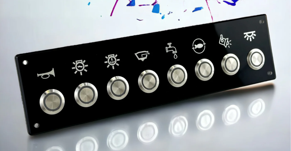
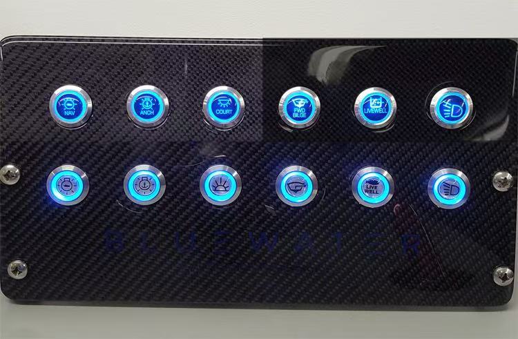
Best Switch Types for Industrial, Vehicle, and Marine Applications
Top picks by sector:
- Industrial: IP67-rated stainless steel push buttons and toggles for wash-down areas.
- Vehicle: Compact rocker switches with glove-friendly actuators and vibration-resistant terminals.
- Marine: Sealed illuminated push buttons with corrosion-proof brass housing and nickel plating.
Selecting industry-specific switches maximizes reliability in challenging environments.
Panel mount switch wiring requires clear identification of terminals, correct tool usage, and adherence to safety standards. Whether you need simple on/off control or multi-function illuminated switches, the steps above guide precise connections, testing, and troubleshooting. Choosing the right specifications and leveraging Langir’s OEM/ODM customization ensures your control panels perform reliably in industrial, vehicle, or marine settings. For tailored bulk solutions and expert support, visit our Panel Switches Category or reach out via our Contact page.