EN
EN
Industrial control panels rely on illuminated industrial switches to provide both reliable power switching and immediate visual feedback, even in demanding environments. Improper wiring can result in critical downtime, equipment malfunction, or significant safety hazards—challenges no industrial operation can afford. This comprehensive guide offers clear, actionable wiring procedures for 2-pin through 6-pin illuminated switches, alongside essential tools, critical safety protocols, rigorous testing methods, compliance with industry standards, and strategic purchasing insights. This guide will equip you with essential knowledge on:
- Understanding the Functionality and Design of Illuminated Industrial Switches
- Essential Tools, Personal Protective Equipment, and Adherence to Wiring Standards
- Step-by-Step Wiring Procedures for Diverse Pin Configurations
- Rigorous Testing, Effective Troubleshooting, and Preventing Common Wiring Errors
- Navigating Environmental Factors, IP Ratings, and Industry Compliance
- Strategic Selection and Customization of Bulk Switches for Industrial Facilities
Understanding the Functionality and Design of Illuminated Industrial Switches
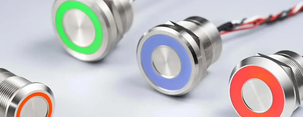
An illuminated industrial switch is a heavy-duty control device that integrates an LED indicator to display circuit status, significantly enhancing operator feedback and process monitoring. Internally, the actuator engages robust metal contacts to establish or interrupt the load circuit, while the integrated LED element draws a minimal current—typically from the same power source or a dedicated low-voltage supply—to illuminate. This dual functionality substantially improves operational safety and efficiency by visually confirming circuit engagement without requiring additional instrumentation.

Get a quote for custom LED push button switches from Langir
Key Components of an Illuminated Industrial Switch
Every illuminated industrial switch comprises three fundamental components: the actuator, the contact assembly, and the LED illumination module.
These components operate in unison, ensuring that when the switch is actuated, the contacts change state and the LED immediately indicates the circuit condition, preparing you for accurate wiring procedures.
Common Types of Illuminated Industrial Switches in Industry
Industrial operations utilize various illuminated switch types, each specifically engineered for distinct control strategies and durability requirements.
Selecting the appropriate switch type simplifies wiring logic and guarantees consistent feedback within your industrial environment.
Impact of Pin Configurations on Wiring
The specific number of pins dictates the precise method for connecting power, load, ground, and LED leads.
A thorough understanding of these pin assignments is paramount for preventing miswiring and ensuring reliable illumination as you proceed to detailed step-by-step procedures.
Essential Tools and Safety Precautions for Wiring Illuminated Industrial Switches
Wiring illuminated switches necessitates both the correct tools and stringent safety measures to safeguard personnel and equipment integrity.
Required Tools for Proper Wiring
You will require essential hand and testing tools to ensure accuracy and operational efficiency:
- Precision wire strippers calibrated for conductor gauge
- Comprehensive electrician’s screwdriver set (flat-head and Phillips)
- Digital multimeter with continuity and voltage measurement functions
- Crimping pliers or a soldering iron (as dictated by terminal type)
These tools ensure precise conductor preparation, secure electrical connections, and reliable circuit verification prior to energization.
Critical Safety Measures During Wiring Operations
De-energizing the power source and proper grounding are non-negotiable steps to prevent electrical shocks and arc faults:
- Always disconnect the circuit at the breaker or main switch before commencing wiring.
- Utilize a certified voltage tester to confirm the complete absence of live voltage.
- Wear appropriate insulated gloves and certified safety glasses.
- Maintain a clear and organized workspace, and strictly adhere to lockout/tagout procedures.
Implementing these precautions rigorously protects installers and ensures compliance with corporate safety policies.
Application of Industrial Safety Standards to Wiring Practices
Industrial switch wiring must conform to recognized standards to guarantee operator safety and equipment reliability.
Industrial Control Panel Standards
Industrial control panels must strictly adhere to specific standards to ensure paramount operator safety and unwavering equipment reliability. These standards encompass various critical aspects, including comprehensive testing for heat resistance, shock protection, and short-circuit prevention, alongside contact durability, insulation integrity, and established electrical safety protocols within industrial workplaces.
Underwriters Laboratories (UL), UL 508: Standard for Industrial Control Equipment
This standard is highly relevant to this article as it underscores the critical importance of adhering to stringent safety and performance standards when wiring illuminated industrial switches.
Wiring Procedures for Diverse Illuminated Industrial Switches
Wiring methodologies vary based on pin count and desired illumination control. Follow these concise, actionable procedures for each switch configuration.

Get a quote for custom LED push button switches from Langir
Wiring a Basic 2-Pin Illuminated Industrial Switch
A 2-pin switch lacks dedicated LED pins; illumination is integrated directly into the main circuit.
- Accurately identify pin 1 (common) and pin 2 (load).
- Connect the positive lead from the power source to the common pin.
- Attach the positive lead of the load device to the load pin.
- Connect the negative side of both the power source and the load together at the ground reference.
This configuration simultaneously powers both the contacts and the LED, providing on-state illumination without requiring additional wiring.
Wiring a 3-Pin Illuminated Switch for Independent Illumination Control
A 3-pin switch features a separate LED circuit for independent status indication.
- Connect the power positive to the COM terminal.
- Connect the load positive to the NO (Normally Open) terminal.
- Attach the LED positive lead to the dedicated LED terminal.
- Join the common negative from the power source and the LED at the chassis ground.
Separating the LED and contact circuits offers clearer status control and minimizes potential load interference.
Wiring a 4-Pin Illuminated Push Button Switch with Isolated LED Control
A 4-pin switch provides complete isolation between the contact and LED power circuits.
- Connect the power positive to the COM terminal.
- Connect the NO/NC terminal to the load positive.
- Connect the LED+ terminal to a switched low-voltage supply positive.
- Connect the LED- terminal to the low-voltage supply negative.
Independent circuits allow for the use of different voltages for illumination and switching functions, enhancing flexibility.
Wiring Multi-Pin (5/6-Pin) Illuminated Switches for Complex Circuits
Advanced multi-pin switches support dual loads and intricate indicator combinations.
- Precisely identify COM, NO1, NC1, NO2, NC2, and LED terminals.
- Connect the power positive to the COM terminal.
- Route NO1 and NO2 to their respective loads requiring power in alternate states.
- Connect NC1/NC2 to loads that require de-energizing when the switch activates.
- Wire LED+ and LED- to the appropriate auxiliary power supply.
This sophisticated setup manages multiple control circuits within a single operator interface, optimizing panel space and enhancing overall functionality.
Testing and Verification Procedures for Illuminated Industrial Switch Wiring
Following wiring, it is imperative to confirm both switch operation and illumination to prevent undetected faults.
Steps to Test Switch Functionality
Utilize continuity and load tests to ensure proper contact operation:
- With power disconnected, use the multimeter in continuity mode between COM and NO/NC.
- Actuate the switch and verify that the meter tone indicates contact closure on the NO (Normally Open) terminal.
- Energize the circuit and confirm that the load device activates correctly.
This sequence rigorously proves that both mechanical and electrical pathways are fully intact.
Verifying Proper LED Illumination
Voltage checks and polarity confirmation validate indicator performance:
- Measure the voltage across LED+ and LED-; it should precisely match the rated voltage.
- Confirm illumination when the switch closes (or as intended if a separate supply is used).
- Briefly reverse polarity (if the LED fails to illuminate) to ensure correct wiring orientation.
Accurate LED confirmation signals precise status mapping for operators.
Troubleshooting Methods for Common Wiring Issues
When illumination or load control malfunctions, systematically trace these common fault patterns:
- No light but contact switches → Indicates miswired LED feed or a faulty LED component.
- No contact closure → Suggests a broken actuator link or corroded terminal.
- Intermittent operation → Points to a loose crimp connection or damaged wire insulation.
Systematically isolating each circuit path restores consistent switch behavior and reliability.
Preventing Common Wiring Mistakes and Ensuring Long-Term Reliability
Preventing errors is as crucial as the wiring process itself—adopting best practices ensures long-term operational reliability.
Wiring Errors Leading to Illumination Failure
Incorrect polarity, missing ground reference, or overloaded circuits frequently cause LED illumination failures:
- Swapping LED+ and LED- leads reverses polarity, preventing illumination.
- Omitting a common negative connection leaves the LED unpowered.
- Utilizing the same feed for heavy loads can cause voltage drop below the LED’s operational threshold.
Avoid these faults by clearly labeling all wires and conducting thorough testing before final enclosure.
Identifying and Rectifying Switch Malfunctions
Regular inspection allows for early detection of loose terminals and damaged conductors:
- Visually inspect all terminal screws for proper tightness and absence of corrosion.
- Perform a gentle wiggle test on each connection under no-load conditions.
- Promptly replace any bent or frayed wires that compromise contact integrity.
Timely maintenance prevents minor issues from escalating into critical system failures.
Best Practices for Ensuring Long-Term Durability
Robust installation techniques and meticulous cable management protect switch longevity:
- Route wires with adequate strain relief to prevent pull-outs and damage.
- Utilize protective conduit or braided sleeves in areas prone to high vibration.
- Properly seal all panel entries to maintain specified IP ratings against dust and moisture ingress.
Adopting these practices ensures illuminated switches perform reliably and consistently in demanding industrial settings.
Influence of Industrial Standards and Environmental Factors on Wiring Practices
Adhering to industry standards and adapting to environmental stresses ensures the enduring performance of switch circuits in industrial conditions.
Get a quote for custom LED push button switches from Langir
Relevant Industrial Safety and Wiring Standards
Switch wiring must strictly align with both electrical and mechanical regulatory requirements:
- IEC 60947 for the durability and performance of low-voltage switchgear.
- UL 508 for the certification and safety of industrial control panel equipment.
- EN 50155 for electrical applications within railway rolling stock.
Conformance to these rigorous standards significantly reduces liability and enhances operational uptime.
Impact of IP Ratings on Switch Installation and Wiring
Ingress Protection (IP) ratings precisely define a switch’s resistance to dust, water, and other external forces:
Ingress Protection (IP) Ratings
IP ratings are paramount for determining the level of protection an enclosure provides against environmental factors such as dust and water. These ratings are essential for ensuring the longevity and reliable performance of electrical components across diverse industrial settings.
International Electrotechnical Commission (IEC), IEC 60529: Degrees of protection provided by enclosures (IP Code)
This citation supports the article’s discussion on how IP ratings critically influence the selection and installation of illuminated industrial switches, particularly in environments exposed to dust or water.
Environmental Conditions Wiring Must Withstand
Industrial wiring is frequently exposed to thermal cycling, significant vibration, and electrical noise:
- Utilize high-temperature insulated conductors in environments such as ovens or heat-affected zones.
- Secure cables rigorously against vibration to prevent conductor fatigue and failure.
- Properly ground shields to minimize electromagnetic interference from motors and relays.
Designing for these challenging factors ensures circuit stability and the unwavering reliability of illuminated indicators.
Selecting the Optimal Illuminated Industrial Switch for Your Application
Choosing the correct switch guarantees safety, functionality, and seamless integration into your control system.
Key Features to Consider When Selecting a Switch
Evaluate technical specifications that precisely align with your process requirements:
- Voltage and current rating accurately matched to your load demands.
- Terminal type (screw, solder lug, quick-connect) for ease of installation and maintenance.
- Diverse LED color options for clear signal differentiation and operational clarity.
- Bushing diameter and panel thickness compatibility for secure mounting.
Considering these critical features upfront streamlines installation and optimizes operational performance.
Enhancing Industrial Switch Performance Through Customization
OEM/ODM options enable you to tailor switches to your exact operational needs:
- Custom legends or color-coded actuators for intuitive and error-free operation.
- Unique LED intensities or specialized blink patterns for distinct alerts.
- Branded bezels and robust stainless steel finishes for harsh industrial environments.
Custom configurations from Langir reduce installation errors and support consistent brand identity.
Procuring Bulk Illuminated Industrial Switches
For large-scale applications demanding uniform quality and expedited delivery, partner with a proven manufacturer.
Contact Langir for Bulk Orders to request a Custom Switch Quote and explore our comprehensive OEM/ODM capabilities that align precisely with your production volume and stringent specification demands.
With meticulous selection, precise wiring, and unwavering adherence to safety standards, illuminated industrial switches will deliver reliable control and clear visual feedback for years of dependable service.