EN
EN

 10/09/2025
Facing challenges wiring a smart switch in older homes lacking a neutral conductor? Integrating a capacitor is the key to banishing that persistent LED flicker. It provides the minimal, steady current needed to keep your switch’s electronics powered when the light is off. This comprehensive guide walks you through why a capacitor is indispensable, precisely how and where to wire it, integrating capacitive touch interfaces, troubleshooting common flicker or false trigger issues, exploring industrial advantages, and dissecting circuit schematics—all presented in clear, actionable steps. Whether you’re a seasoned electrical professional or an industrial integrator seeking high-volume capacitive switch solutions, this article equips you with practical wiring techniques, maintenance insights, and advanced customization options.
The Crucial Role of a Capacitor in No-Neutral Smart Switch Setups
A capacitor acts as a miniature energy reservoir, storing and releasing electrical charge. In smart switch installations without a neutral wire, it ensures a consistent, albeit small, current flow to power the switch’s internal electronics. This continuous supply prevents the voltage fluctuations that can cause operational interruptions and the annoying flicker in LED bulbs. By installing a capacitor across the load, you effectively create a stable return path, mimicking a neutral conductor and keeping your smart switch fully operational.

Get a quote for custom capacitive switches from Langir
Why Smart Switches Need Capacitors (No Neutral Required)
A capacitor delivers a small, continuous current to power a smart switch’s internal electronics when a neutral wire isn’t available, preventing voltage dips that lead to LED flicker. Connecting a capacitor across the load establishes a stable return path, effectively acting like a neutral conductor.
This explanation lays the groundwork, clarifying the fundamental necessity of capacitors for the article’s central theme.
Understanding Capacitance in Smart Switch Operation
Capacitance measures a component’s ability to store electrical charge. For smart switches, this translates to a vital energy buffer. By smoothing out variations in line voltage, capacitance ensures the switch’s microcontroller maintains stable wireless connectivity and responds promptly to commands. This buffering capability also supports efficient low-power standby modes, significantly enhancing overall switch reliability.
Beyond stability, the next critical advantage is preventing LED flicker.
How Capacitors Eliminate LED Flicker in No-Neutral Smart Switches
When wired in parallel with your LED load, a capacitor absorbs sudden voltage spikes and compensates for current dips. This action smooths the electrical waveform, preventing the rapid on-off cycles that cause flickering in LED lights.
- It releases stored energy to counteract voltage sags.
- It manages inrush current to LEDs, preventing abrupt power surges.
- It filters out high-frequency noise, stopping false activations of the switch’s sensor.
By stabilizing the voltage supply, this method effectively eliminates visible flicker and protects both the LED driver and the smart switch’s sensitive circuitry.
Selecting the Optimal Capacitor Types for Smart Switch Stability
Here’s a breakdown of common capacitor types suitable for no-neutral smart switch installations, chosen for their safety and longevity.
Understanding X2 Safety Capacitor Ratings
X2 safety capacitors are engineered for electronic devices and typically rated at 275VAC. They are frequently employed in applications like air conditioning units and network routers.
Recommended Capacitors for Stable Smart Switches
For environments operating at line voltage, X2 safety film capacitors are generally the preferred choice, ensuring both regulatory compliance and effective flicker suppression. Other suitable options include polyester film and ceramic capacitors.
Opting for an X2-rated safety capacitor is typically advised for line-voltage applications to guarantee adherence to regulations and dependable flicker mitigation.
Step-by-Step Capacitor Wiring for No-Neutral Smart Switches
Correctly installing a capacitor involves precise placement, the right tools, and clear, sequential wiring steps to ensure both safety and optimal performance. Follow this straightforward wiring guide to eliminate flicker, maintain connectivity, and meet industry standards.

Get a quote for custom capacitive switches from Langir
Optimal Capacitor Placement in the Circuit
The capacitor should be installed in parallel with the load, directly at the light fixture. Connect it between the live (L) and load (L1) conductors that supply the LED bulb. Positioning it at the fixture ensures it directly addresses voltage fluctuations at the source of the flicker, bypassing any concealed wiring junctions within the walls.
Capacitor Wiring Location for No-Neutral Smart Switches
Install the capacitor in parallel with the load at the fixture end, connecting it between the live (L) and load (L1) conductors feeding the LED bulb. This placement ensures direct voltage stabilization right where flicker originates.
This section provides the critical instructions for capacitor placement, a key practical element of the article.
Essential Tools and Materials for Capacitor Installation
Gather these necessary items before you begin to ensure a smooth and safe installation process:
- A multimeter for confirming voltage and continuity
- Insulated wire strippers and cutters for precise conductor preparation
- A set of screwdrivers with insulated handles
- Wire connectors or terminal blocks rated for 300 VAC
- The selected X2-rated safety capacitor (typically 0.1–0.47 µF)
Having these tools readily available will prevent interruptions and minimize risks during the electrical work.
Detailed Wiring Procedure for Capacitor Integration
Follow these sequential steps to correctly install the capacitor in parallel with your smart switch’s LED load:
- Deactivate the circuit breaker and confirm zero voltage using a multimeter.
- Open the fixture’s junction box and identify the live (L) and load (L1) wires.
- Carefully strip 6–8 mm of insulation from both conductors.
- Connect one capacitor lead to the live conductor (L) using an appropriate crimp connector.
- Connect the other capacitor lead to the load conductor (L1) at the same junction point.
- Secure all connections, neatly arrange the wiring, and replace the junction box cover.
- Restore power to the circuit and verify that the switch maintains a stable connection and the LED operates without flicker.
Successfully completing these steps will result in a flicker-free circuit that effectively replicates a neutral return path, enhancing smart switch performance.
Connecting the Capacitor in Parallel with LED Bulbs Explained
Wiring in parallel means that each lead of the capacitor connects to the same points as the lamp’s live and load connections. One lead connects to the fixture’s hot supply, and the other connects to the lamp’s input. This direct connection instantly provides charge when the bulb’s current momentarily drops, eliminating flicker directly at its source.
Safe Handling of Electrical Components During Installation
Always de-energize circuits before starting work. Wear appropriate personal protective equipment (PPE), including insulated gloves and eye protection. Verify zero voltage before making any contact and maintain clear, labeled separation between conductors. Implementing lock-out/tag-out procedures and adhering to local electrical codes are crucial for preventing electric shock and fire hazards.
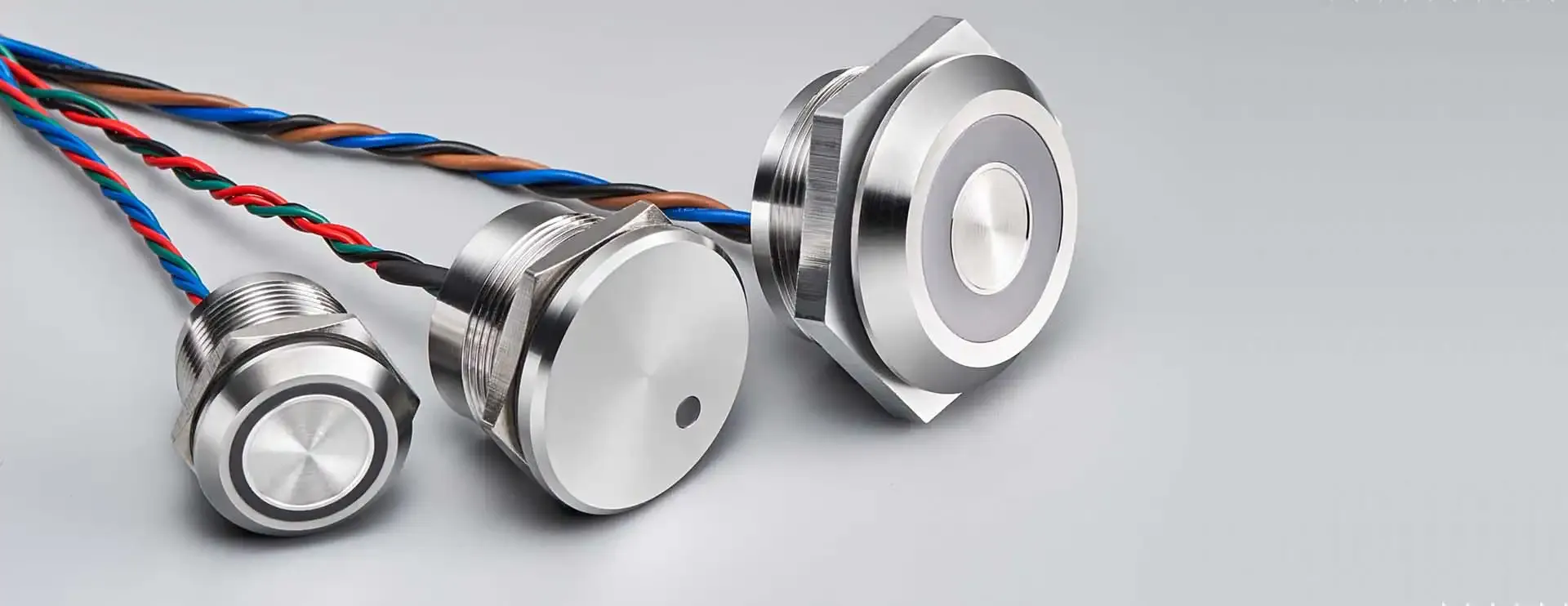
Integrating Capacitive Touch Switches into Smart Home Ecosystems
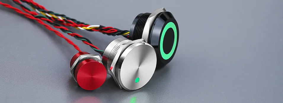
A capacitive switch detects touch by sensing changes in an electric field, rather than relying on mechanical movement. This makes them perfect for sleek, sealed smart panels that resist dust and moisture, ideal for modern industrial control systems.
Get a quote for custom capacitive switches from Langir
What Defines a Capacitive Switch and Its Touch Detection Mechanism?
A capacitive switch utilizes electrodes and a dielectric layer to form a small capacitor. When a finger approaches, the capacitance of the electric field changes, signaling the switch’s sensor chip. This technology enables silent, wear-free operation and supports advanced interactions like gestures and multi-touch controls.
Following the sensing principle, the next logical step is understanding how to connect these electrodes to the PCB.
Connecting Capacitive Switch Electrodes to PCBs in Smart Switches
Begin by precisely aligning the switch’s electrode pad with its corresponding sensing input on the PCB. Next, solder fine-gauge shielded wires from the electrode pad to the PCB’s capacitive input pin, ensuring minimal signal interference and stable readings. Finally, fine-tune the sensitivity through the switch’s firmware or an onboard trim potentiometer for accurate touch recognition.
Advanced calibration naturally leads into the areas where these switches truly shine: industrial applications.
Prominent Industrial Uses for Capacitive Switches
- Sanitary controls in food processing equipment, where sealed surfaces prevent contamination.
- Interactive kiosks and vending machines requiring robust, vandal-resistant panels.
- Medical device interfaces designed for easy cleaning and sterilization.
- Automated assembly lines where dust or oil could impede mechanical buttons.
Key Industrial Applications for Capacitive Switches
Capacitive switches are utilized in hygienic controls for food processing, interactive kiosks, medical device interfaces, and automated assembly lines.
This section provides concrete examples of capacitive switch applications, reinforcing the article’s discussion on industrial relevance.
Troubleshooting Common Issues in Capacitive Smart Switch Installations
When flicker or unresponsiveness persists, a methodical diagnostic approach helps pinpoint the root cause and verify component integrity, restoring optimal performance.
Get a quote for custom capacitive switches from Langir
Why Might My Smart Switch Still Flicker After Capacitor Installation?
Persistent flicker can often be attributed to an undersized capacitor, multiple LED strings wired in parallel, or compromised connection integrity. Double-check that you are using an X2-rated 0.1–0.47 µF capacitor, ensure all crimp connections are solid, and if multiple bulbs are on the same circuit, consider installing a capacitor for each fixture to manage distributed loads effectively.
Resolving Persistent LED Flicker
Lingering flicker issues may stem from an undersized capacitor, multiple parallel LED strings, or poor connection quality. Confirm you’re using an X2-rated 0.1–0.47 µF capacitor, verify secure crimp connections, and if multiple bulbs are involved, consider adding a capacitor per fixture to handle the load distribution.
Diagnosing Unresponsive or False Triggering Capacitive Switches
Start by ensuring the sensing electrode is clean and securely attached. Next, measure the baseline capacitance using a meter; unexpectedly low readings may indicate a problem with the PCB trace or pad. Finally, test for electrical noise by temporarily disconnecting nearby high-frequency devices and recalibrating the sensitivity settings.
Best Practices for Maintaining Capacitive Switch Performance
- Keep electrode surfaces free from dust and conductive contaminants.
- Recalibrate touch thresholds annually or following any panel modifications.
- Regularly inspect solder joints for signs of cold joints or corrosion.
- Utilize shielded cables for extended electrode leads to mitigate EMI interference.
Consistent preventive maintenance ensures reliable response times and minimizes operational downtime.
Advantages of Capacitive Switches with Capacitors in Industrial Smart Systems
Combining capacitive touch interfaces with stabilizing capacitors significantly enhances user experience and system resilience, delivering the robust reliability that industrial environments demand.
Get a quote for custom capacitive switches from Langir
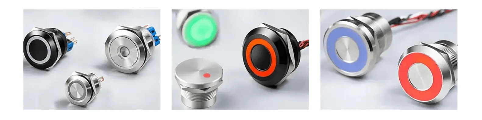
How Capacitive Switches Elevate Durability and User Experience
Capacitive switches eliminate mechanical wear and tear, offering superior resistance to harsh conditions. Coupled with capacitors that ensure stable power delivery to the sensor, they enable seamless operation, intuitive touch feedback, and a sleek, sealed front-panel design that simplifies cleaning and hygiene protocols.
Industrial Benefits of Capacitive Touch Switches
Capacitive switches feature no moving parts, resist wear, and withstand demanding environments, while capacitors provide consistent power to the sensor. Together, they facilitate smooth operation, intuitive touch feedback, and a sleek, sealed front-panel design that simplifies cleaning and hygiene.
The Value of Customized Capacitive Switch Solutions for Industry
Custom layouts, logo-engraved overlays, and specialized sensing parameters allow you to tailor each panel to precise factory or medical specifications. Bulk orders unlock significant cost savings, and partnering with an experienced manufacturer ensures rapid prototyping and punctual production schedules.
Illustrative Case Studies of Successful Capacitive Switch Integration
- A medical equipment OEM replaced traditional buttons with sealed capacitive panels, achieving a 70% reduction in maintenance requirements.
- An automotive manufacturing plant implemented bulk capacitive floor-mount controls, decreasing failure rates in wash-down zones by 90%.
- A consumer appliance brand integrated capacitive glass touch plates in high-volume production, enhancing brand perception and reducing warranty claims.
Essential Wiring Diagrams and Circuit Schematics for Smart Switch Capacitor Installation
Detailed schematics provide a clear roadmap of every conductor, component, and connection, facilitating efficient and error-free installations.
Get a quote for custom capacitive switches from Langir
Interpreting and Utilizing Circuit Diagrams for Capacitor and Smart Switch Wiring
Circuit diagrams use standardized symbols—lines for conductors, zigzags for resistors, parallel lines for capacitors—to illustrate component interconnections. By tracing the live and load paths, you can confirm correct capacitor placement at the fixture and ensure the switch’s power input aligns with the hot feed.
Availability of Downloadable Wiring Schematics for No-Neutral Smart Switch Capacitor Setups
Yes, downloadable PDF schematics illustrating single-pole, multi-bulb, and multi-gang configurations are available. Contact our team to receive customized schematics tailored to your specific installation environment.
Understanding Semantic Triples in Wiring Diagrams
Accessing Professional Support and Bulk Capacitive Switch Solutions
For seamless integration, expert design consultation, and volume pricing on capacitive touch switches with integrated capacitance stabilization, partner with Langir’s dedicated team.
How to Request Custom Capacitive Switch Manufacturing and Bulk Pricing
To obtain a bulk quote for capacitive switches or to discuss custom front-panel designs, please request a bulk quote for capacitive switches.
Langir’s Support for Smart Switch Capacitor Integration
Langir offers on-site technical training, comprehensive wiring blueprints, on-call troubleshooting assistance, and firmware calibration guidance to ensure effortless capacitor integration and dependable smart switch performance.
Finding Installation Guides and Troubleshooting Resources from Langir
Visit our resource center or contact us directly to access step-by-step manuals, detailed wiring schematics, and maintenance checklists specifically designed for your smart switch project requirements.
Capacitor-enhanced smart switch installations effectively resolve flicker issues, enable no-neutral wiring configurations, and unlock the full potential of capacitive touch control. From fundamental capacitance principles to advanced wiring diagrams and industrial customization options, this guide provides the essential knowledge for implementing reliable, durable smart switch systems that elevate user experience and maximize operational uptime. Ready to advance your next project? Connect with Langir’s specialists for bulk solutions, bespoke designs, and hands-on support today.